
Improved drinking device

A drinking water equipment and an improved technology, applied in beverage preparation devices, home appliances, applications, etc., can solve the problems of reducing the experience of taking boiled water, making it difficult to make full use of water dispensers, etc., and achieve the effect of meeting the needs of regular drinking

Inactive Publication Date: 2020-12-22
NINGBO FOTILE KITCHEN WARE CO LTD
View PDF6 Cites 0 Cited by
  • Summary
  • Abstract
  • Description
  • Claims
  • Application Information

AI Technical Summary

Problems solved by technology

[0004] However, the water dispenser in the utility model patent CN209285062U also has deficiencies: as the circulation pump provides the power of water circulation, the boiling water heated by the heating element in the first tank can flow into the second tank again, so as to improve the temperature of the second tank. The temperature of the water in the body makes the first tank contain boiled water, and the second tank contains warm water with a higher temperature, that is, the two tanks holding water become "boiled water + warm water" mode
But, if in the peak period of using boiled water, the water intake end that this water dispenser can provide boiled water (that is, the pipeline where the first water outlet valve is located) is still directly connected to the water intake pipeline of the first tank, and connected to the second tank. The water intake end of the body (that is, the pipeline where the second water outlet valve is located) cannot be fully utilized to provide boiled water, and it is difficult to make full use of each water intake end of the water dispenser, which reduces the user's experience when taking boiled water

Method used


Image

  • Improved drinking device
  • Improved drinking device

Examples


Embodiment Construction

[0041]The present invention will be described in further detail below in conjunction with the embodiments of the drawings.

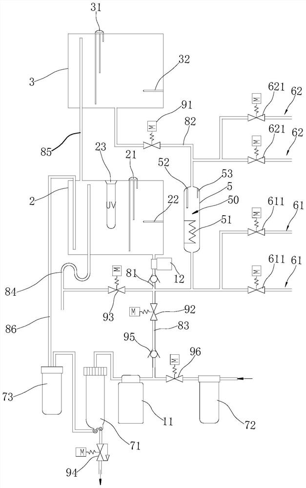
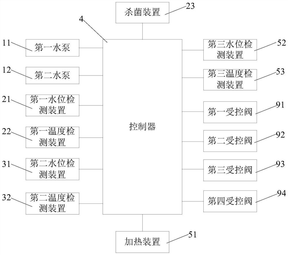
[0042]Such asfigure 1 As shown, this embodiment provides an improved drinking water device, specifically a drinking water machine. The water dispenser of this embodiment includes:

[0043]The first water pump 11 draws water from an external water source; the external water source is usually a tap water pipe, and the external water source is also called raw water;

[0044]The first water storage tank 2 has a first water level detection device 21 for detecting the water level in the first water storage tank and a first temperature detection device 22 for detecting the water temperature in the first water storage tank; wherein, the water inlet end of the first water storage tank 2 passes The water outlet of the first water pump 1 is directly or indirectly connected, and a water purification device 71 is provided between the water outlet of the first water pump 1 and the w...


PUM


Abstract

The invention relates to an improved drinking device. The improved drinking device comprises a first water pump, a first water storage tank and a second water storage tank, wherein the first water storage tank is connected with the first water pump, and the first water storage tank communicates with the second water storage tank. The improved drinking device is characterized by further comprisinga controller and a heater with a water containing cavity, wherein the water containing cavity is connected with the water outlet end of the first water storage tank and the water inlet end of the second water storage tank through pipelines respectively; the heater is provided with a heating device for heating water in the water containing cavity; the first water storage tank, the second water storage tank and the heater can form a circulating water path; the water outlet end of the first water storage tank and the water inlet end of the water containing cavity are connected with at least one first water taking end respectively; and the water inlet end of the second water storage tank and the water outlet end of the water containing cavity are connected with at least one second water takingend respectively. The controller works on the first water pump and the heating device, so that the water storage modes of the two water storage tanks are changed into a boiled water and warm water mode or a boiled water and boiled water mode, and the drinking requirement of people for boiled water in the drinking peak period is met.

Description

Technical field[0001]The invention relates to the field of drinking water equipment, in particular to an improved drinking water equipment.Background technique[0002]The existing drinking water equipment mainly provides boiling water and room temperature water. With different seasons, users have different temperature requirements for drinking water. For example, when people use drinking water equipment to fetch water in cold winter, people have more demand for boiling water, while in summer, people have more demand for water at room temperature.[0003]Chinese utility model patent CN209285062U discloses a water dispenser, which includes a first tank, a second tank, a circulating pump, a first liquid level detector for detecting the water level in the first tank, and a second tank for detecting water The second liquid level detecting part of the water level and the controller respectively connected to the circulating pump, the first liquid level detecting part and the second liquid leve...

Claims


Application Information

Patent Timeline
IPC IPC(8): A47J31/00A47J31/44A47J31/46A47J31/56
CPCA47J31/00A47J31/4403A47J31/56A47J31/461
Inventor 姜亚
Owner NINGBO FOTILE KITCHEN WARE CO LTD
Learn More