Sputum suction robot suite

A technology of robots and kits, applied in the direction of respirators, suction devices, hypodermic injection devices, etc., can solve the problems of inconvenient and quick connection, failure to realize full automation, and drop in blood oxygen of patients, and achieve the effect of reducing the risk of cross-infection

Pending Publication Date: 2020-12-22
崇好科技有限公司
View PDF3 Cites 0 Cited by
  • Summary
  • Abstract
  • Description
  • Claims
  • Application Information

AI Technical Summary

Problems solved by technology

But in above-mentioned device all do not take into account: 1, transmission airtight sputum suction tube needs to pay attention to aseptic principle, in use, because motor and transmission device are integrated design, when changing patient, the disinfection of transmission device is very difficult convenient
2. When using the sputum suction tube to suck sputum, it is necessary to disconnect the oxygen supply of the ventilator, so that the blood oxygen of the patient will drop, and the life of the patient will be endangered.
3. The suction tube needs to be flushed after sucking sputum. In the previous patent, the closed suction tube cannot be used for automatic flushing operation. Manual intervention is required, and full automation has not been realized.
4. The manipulator and linear guide type sputum suction robot are inconvenient to install in clinical use due to their large size
5. The currently popular suction tubes and ventilator connection tees in the market cannot be easily and quickly connected. It is necessary to optimize the ventilator connection tee and the closed sputum suction magazine connected to the suction robot

Method used


Image

  • Sputum suction robot suite
  • Sputum suction robot suite
  • Sputum suction robot suite

Examples


Embodiment Construction

[0029] The present invention will be described in further detail below in conjunction with the accompanying drawings and specific embodiments.

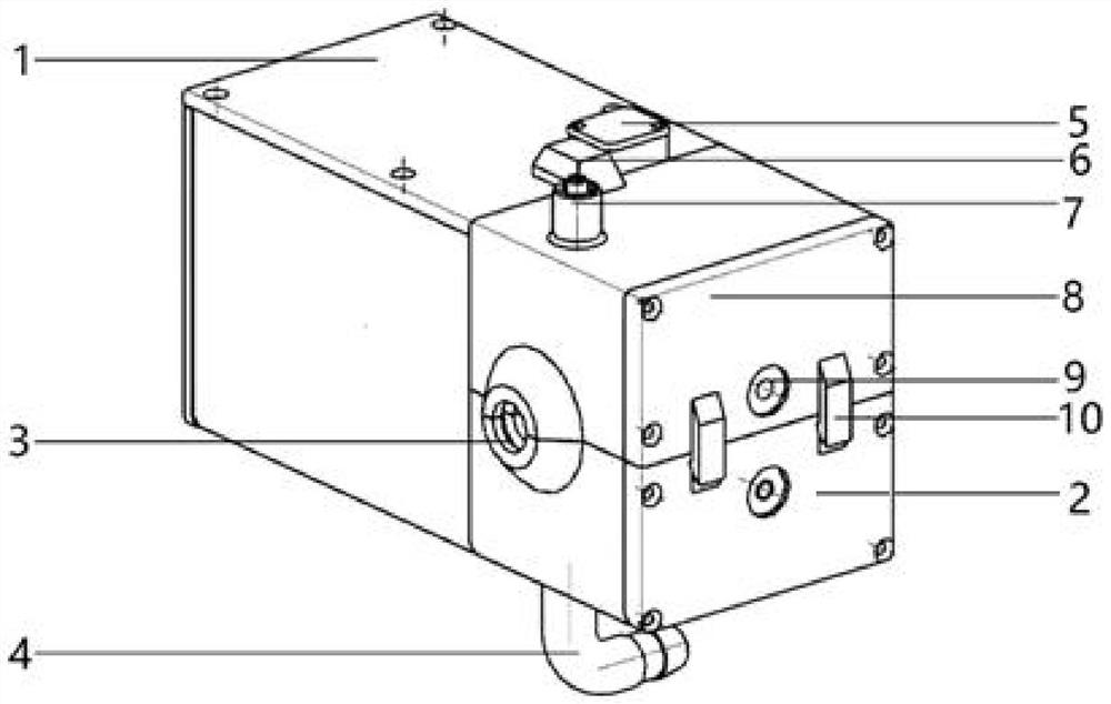
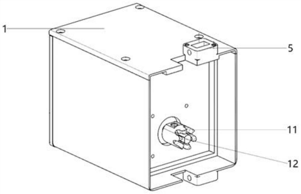
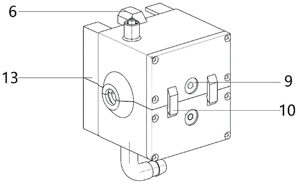
[0030] see figure 1 , in a preferred embodiment of the present invention, the present invention includes a motor end and a transmission end, the transmission end includes an upper transmission end and a lower transmission end, the motor end includes a motor end housing 1, the motor is arranged in the motor end housing 1, and the upload The sending end includes an upper transmission end housing 8, the lower transmission end includes a lower transmission end housing 2, the upper surface of the motor end housing 1 is provided with a spring buckle 5, and the upper surface of the upper transmission end housing 8 is correspondingly provided with The buckle 5 is connected to the spring slot 6, the outer side of the lower transmission end housing 2 is provided with a side plate slot, and the outer side of the upper transmission end housing 8 ...


PUM


Abstract

The invention relates to a sputum suction robot suite. The sputum suction robot suite comprises a motor end and a conveying end, wherein the motor end comprises a motor; the conveying end comprises anupper conveying end body and a lower conveying end body, the upper conveying end body is arranged above the lower conveying end body, the upper conveying end body comprises an upper conveying end shell, an upper gear and a sputum suction tube conveying upper roller connected with the upper gear, and the upper gear and the sputum suction tube conveying upper roller are arranged in the upper conveying end shell; the lower conveying end body comprises a lower conveying end shell, a lower gear and a sputum suction tube conveying lower roller connected with the lower gear, the lower gear and the sputum suction tube conveying lower roller are arranged in the lower conveying end shell, the upper gear is meshed with the lower gear, and the sputum suction tube conveying upper roller is located above the sputum suction tube conveying lower roller; and the motor is connected with the sputum suction tube conveying lower roller or the sputum suction tube conveying upper roller, and a breathing machine three-way pipeline connector and a closed sputum suction tube connector are arranged on the left side face and the right side face of the lower conveying end shell and / or the upper conveying endshell respectively. The sputum suction robot suite has the advantages that the clinical sterile use requirement can be met, and uninterrupted oxygen supply for a patient can be guaranteed.

Description

technical field [0001] The invention belongs to the technical field of medical equipment, in particular to a sputum suction robot kit. Background technique [0002] Maintaining the patency of the artificial airway is the basic requirement for maintaining the life activities of mechanically ventilated patients. Patients using mechanical ventilation often block the airway with sputum, requiring nurses to manually suck the sputum. In my country, the average bed-to-nurse ratio is about 0.5:1. Clinical nurses need to face repeated sputum suction work while completing other nursing work, which greatly increases the nursing workload. Some literature points out that even the clinical endotracheal suction operation of senior nurses in general hospitals only has a correct rate of about 60%. Therefore, the accuracy of clinical sputum suction operation needs to be improved. The sputum suction operation in the artificial airway faces the risk of cross-infection under special circumsta...

Claims


Application Information

Patent Timeline
Patent Type & Authority Applications(China)
IPC IPC(8): A61M1/00A61M16/04
CPCA61M1/0023A61M16/0463A61M1/85A61M1/86
Inventor 朱皓阳冯哲吕毅史爱华谭文君董鼎辉马涛王越陈环王强袁力蓉唐湘王凯玲
Owner 崇好科技有限公司
Why Eureka
Try Eureka