
Intrauterine equipment placer

A technology of placer and uterus, which is applied in the field of medical equipment, can solve the problems of infection, waste of resources, equipment costs, rough movements, etc., and achieve the effects of avoiding cross-contamination, realizing repeated use, and preventing uterine perforation

Pending Publication Date: 2021-10-19
江苏英诺麦德科技有限公司
View PDF8 Cites 0 Cited by
  • Summary
  • Abstract
  • Description
  • Claims
  • Application Information

AI Technical Summary

Problems solved by technology

In addition, infection (endometritis, adnexitis, etc.), irregular bleeding and menstrual disorders may also occur, and may even cause infertility.
[0019] It is not easy to control the angle and depth of the placer when it is inserted into the female uterus. It usually needs to be judged according to the doctor's experience. If it is due to unskilled technique, improper placement or rough action, it may cause uterine perforation, ectopic IUD, etc. problems, or damage to the cervix, endometrium, etc. during implantation
In addition, if the implantation depth is not enough, the position of the IUD in the uterus may be wrong or there may be problems with its fixation, which may cause the IUD to be placed in place or even fall off.
[0020] The placer used in the current intrauterine equipment is generally provided together with the equipment, which is one-time use and does not allow repeated use. Such a design will cause waste of resources and increase the cost of equipment
And reuse the placer, there will be a risk of user cross-infection
[0021] It is precisely because it is usually necessary to judge the state of the placer during use based on the doctor's experience, and if any problem occurs, it may cause huge physical and mental damage to the patient. Therefore, strict training will be carried out before clinical use, which is time-consuming and labor-intensive.

Method used


Image

  • Intrauterine equipment placer
  • Intrauterine equipment placer
  • Intrauterine equipment placer

Examples


Embodiment Construction

[0063] The implementation mode of the present invention is illustrated by specific specific examples below, and those who are familiar with this technology can easily understand other advantages and effects of the present invention from the contents disclosed in this description. Obviously, the described embodiments are a part of the present invention. , but not all examples. Based on the embodiments of the present invention, all other embodiments obtained by persons of ordinary skill in the art without making creative efforts belong to the protection scope of the present invention.

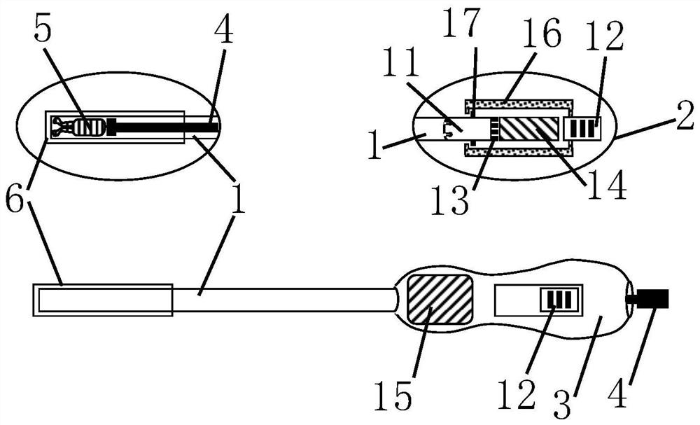
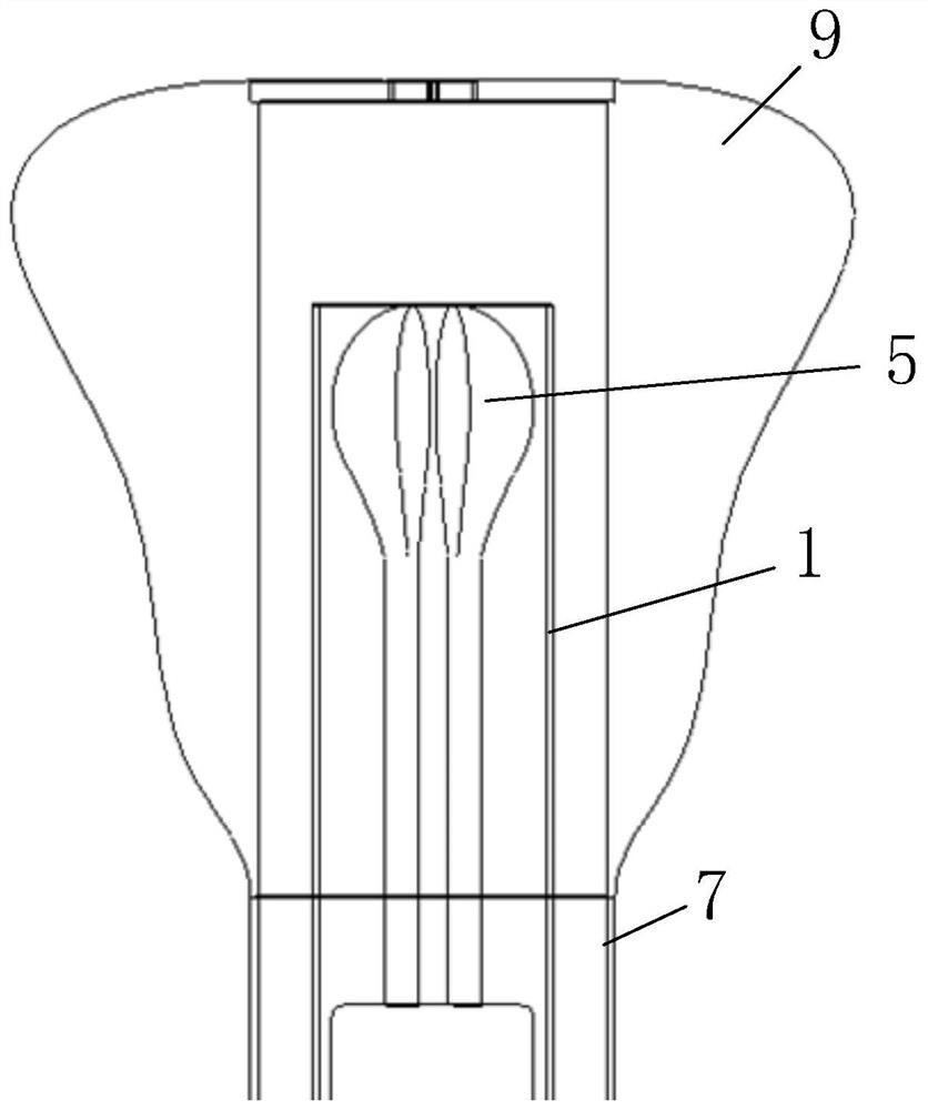
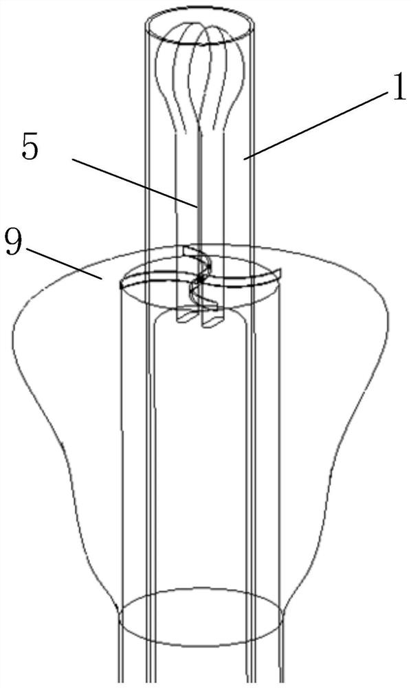
[0064] like Figure 1 to Figure 18 As shown, an intrauterine device placer in the embodiment of the first aspect of the present invention includes a placement tube 1, a base assembly 2, a handle 3, a push rod 4 and a protective layer assembly 6, the handle 3 is provided with a base assembly 2, The protective layer component 6 is sleeved on the placement tube 1, the placement tube 1 is inserted o...


PUM


Abstract

The invention discloses an intrauterine equipment placer which comprises a placement tube, a base assembly, a handle, a push rod and a protective layer assembly, the base assembly is arranged on the handle, the protective layer assembly is arranged on the placement tube in a sleeving mode, and the placement tube is arranged on the handle in an inserted mode and is in sliding connection with the handle through the base assembly; the push rod is inserted into the handle, penetrates through the base assembly and is in sliding connection with the containing pipe, and the push rod is used for fixing the intrauterine implantable equipment. The intrauterine equipment placer belongs to the technical field of medical instruments, and aims at solving the problem that in the prior art, when implanted into the uterus, intrauterine implantable equipment is prone to carrying bacteria or causing pollution. The intrauterine equipment placer has the technical effects that through the arrangement of the protective layer assembly, the placement tube and the intrauterine implantable equipment can be protected when the placement tube passes through the vagina, and then the situation that the outer surface of the placement tube is contaminated or carried bacteria and other pollutants enter the cervix uteri and the uterine cavity is prevented.

Description

technical field [0001] The invention relates to the technical field of medical appliances, in particular to an intrauterine device placer. Background technique [0002] The uterus is one of the important reproductive organs of women. It is an important place for menstruation and pregnant fetus. The uterus is a hollow organ in the center of the pelvic cavity covered by a mucous membrane called the endometrium. From puberty to menopause, the endometrium is affected by ovarian hormones, thickens and sheds periodically to form menstruation. At conception, sperm travels through the uterus to the fallopian tubes. After conception, the uterus is the place where the embryo develops and grows, pregnant with the fetus. During labor, the uterus contracts to expel the fetus and its appendages. These physiological functions are mainly controlled by the estrogen and progesterone secreted by the ovary, which determine the normal cyclical changes in the uterus. It can be seen that the ...

Claims


Application Information

Patent Timeline
IPC IPC(8): A61F6/18
CPCA61F6/18
Inventor 陆世龙黄欣张琦
Owner 江苏英诺麦德科技有限公司
Learn More