Three-jaw chuck clamp for synchronous belt wheel machining

A three-jaw chuck and synchronous pulley technology, applied in the field of mechanical fixtures, can solve the problems of synchronous pulley scrapping, punching failure, low work efficiency, etc., and achieve the effect of meeting the punching requirements, novel structure, and good use effect

Inactive Publication Date: 2020-12-22
盐城市同达机械科技有限公司
View PDF0 Cites 1 Cited by
  • Summary
  • Abstract
  • Description
  • Claims
  • Application Information

AI Technical Summary

Problems solved by technology

[0002] The synchronous pulley needs to be drilled during the processing process. At present, the position mark is first made on the synchronous pulley, and then the synchronous pulley is clamped on the three-jaw chuck and sent to the punching machine for drilling. This punching method is inefficient, and the punching position is prone to deviation, resulting in punching failure or scrapping of the synchronous pulley

Method used


Image

  • Three-jaw chuck clamp for synchronous belt wheel machining
  • Three-jaw chuck clamp for synchronous belt wheel machining
  • Three-jaw chuck clamp for synchronous belt wheel machining

Examples


Embodiment Construction

[0011] The specific content of the present invention will be described in detail below in conjunction with the accompanying drawings and specific embodiments.

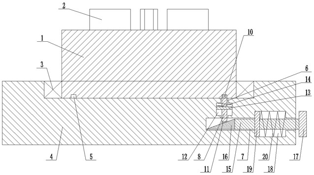
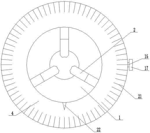
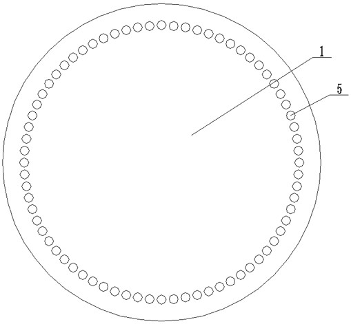
[0012] Such as figure 1 , figure 2 , image 3 As shown, the three-jaw chuck fixture for synchronous pulley processing includes: a three-jaw chuck 1 and three jaws 2 arranged on the three-jaw chuck 1, and the three-jaw chuck 1 is rotated by a bearing seat 3. In the base 4, a plurality of positioning holes 5 are evenly arranged on the lower edge of the three-jaw chuck 1, and one end of the base 4 is provided with a vertical sliding hole 6, and the base at the lower end of the vertical sliding hole 6 4 is provided with a horizontal slide hole 7 interconnected with the vertical slide hole 6, and a vertical push rod 8 cooperating with it is slidably arranged in the vertical slide hole 6, and at the upper end of the vertical push rod 8 A positioning column head 10 that cooperates with the positioning hole 5 is provided, ...


PUM


Abstract

The invention discloses a three-jaw chuck clamp for synchronous belt wheel machining. A three-jaw chuck and three clamping jaws arranged on the three-jaw chuck are included, the three-jaw chuck is rotationally arranged in a base through a bearing pedestal, a plurality of positioning holes are evenly formed in the edge of the lower end of the three-jaw chuck, and a vertical sliding hole is formed in one end of the base. A transverse sliding hole communicating with the vertical sliding hole is formed in the position, at the lower end of the vertical sliding hole, in the base, a vertical ejectorrod matched with the vertical sliding hole is arranged in the vertical sliding hole in a sliding mode, and a positioning column head matched with a positioning hole is arranged at the upper end of thevertical ejector rod. A first inclined wedge is arranged at the lower end, stretching into the transverse sliding hole, of the vertical ejector rod, and a vertical limiting hole communicating with the vertical sliding hole is formed in the portion, in the middle of the vertical sliding hole, of the base.

Description

technical field [0001] The invention relates to a mechanical fixture, in particular to a three-jaw chuck fixture for synchronous pulley processing. Background technique [0002] The synchronous pulley needs to be drilled during the processing process. At present, the position mark is first made on the synchronous pulley, and then the synchronous pulley is clamped on the three-jaw chuck and sent to the punching machine for drilling. This punching method has low work efficiency, and the punching position is prone to deviation, resulting in punching failure or scrapping of the synchronous pulley. Contents of the invention [0003] The technical problem to be solved by the present invention is to provide a three-jaw chuck fixture for synchronous pulley processing which can adjust the punching angle. [0004] In order to solve the above-mentioned technical problems, the technical solution adopted in the present invention is: a three-jaw chuck fixture for synchronous pulley pro...

Claims


Application Information

Patent Timeline
Patent Type & Authority Applications(China)
IPC IPC(8): B23Q16/06B23B31/02
CPCB23B31/02B23Q16/06
Inventor 殷超沈大明殷从新
Owner 盐城市同达机械科技有限公司
Why Eureka
Try Eureka