An automatic feeding punching machine

A technology of automatic feeding and punching machine, applied in the direction of feeding device, manufacturing tool, positioning device, etc., can solve the problems of imperfect continuous punching field, improve punching quality and punching efficiency, and achieve stable and continuous feeding effect. , the effect of promoting the application

Inactive Publication Date: 2020-01-07
海盐三鑫机械有限公司
View PDF13 Cites 0 Cited by
  • Summary
  • Abstract
  • Description
  • Claims
  • Application Information

AI Technical Summary

Problems solved by technology

However, the current hydraulic punching machine is not perfect in the field of continuous punching, and is limited to the continuous punching of some strip metal profiles.

Method used


Image

  • An automatic feeding punching machine

Examples


Embodiment Construction

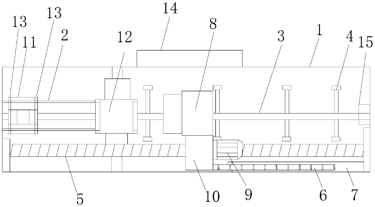
[0014] refer to figure 1 , an automatic feeding punching machine of the present invention, comprising a frame 1, a slide rail 2, a limit rod 3, an auxiliary conveying roller 4, a stroke screw 5, a finishing chain 6, a chain groove 7, a claw feeder 8, and a servo motor 9 , rotating screw sleeve 10, vertical stamping die set 11, horizontal stamping die set 12, auxiliary gripper 13, control center 14, the limit rod 3 is arranged on the top of the frame 1, and the limit rod 3 is horizontally arranged on On the top of the frame 1, several auxiliary conveying rollers 4 are arranged on the frame 1 directly below the stop bar 3, and the head end of the stop bar 3 is provided with a vertical stamping module 11, and the frame 1 The top is provided with a slide rail 2, the vertical stamping die set 11 is installed on the top of the frame 1 through the slide rail 2, the vertical stamping die set 11 is provided with an auxiliary gripper 13, and the vertical stamping die set 11 The right s...


PUM


Abstract

The invention discloses an automatic feed punching machine which comprises a rack, sliding rails, a limiting rod, auxiliary conveying rollers, a stroke screw, an arrangement chain, a chain groove, a claw machine, a servo motor, a rotary screw sleeve, a vertical stamping die set, a horizontal stamping die set, auxiliary clamping devices and a control center. According to the automatic feed punching machine, the punching machine can automatically push pipes needing to be machined; the feed effect is stable and continuous; meanwhile, multi-face synchronous punching can be carried out on the pipes; the punching requirements of the pipes can be fully met; the punching quality and punching efficiency can be improved; and application and popularization are facilitated.

Description

technical field [0001] The invention relates to the technical field of punching equipment, in particular to the technical field of an automatic feeding punching machine. Background technique [0002] Pipes or profiles are widely used in construction, decoration and various products. In order to meet various needs, pipes need to be processed in different ways such as cutting, bending, welding, and opening. Among them, openings have Not a small difficulty; one hole requires a variety of hole types, the second requires the coordination and unity of the holes on the same pipe at a certain angle, the third requires the speed and quality of the hole, and the four requires the accuracy of the hole distance of the hole and multi-dimensionality; there are several ways to open pipes at present, the most primitive is to use a bench drill to open round holes on the pipe, this method cannot meet the requirements of multi-hole type, and it cannot have advantages in speed and quality , Th...

Claims


Application Information

Patent Timeline
Patent Type & Authority Patents(China)
IPC IPC(8): B21D43/12B21D43/08B21D28/28
CPCB21D28/28B21D43/08B21D43/12
Inventor 李斌
Owner 海盐三鑫机械有限公司
Why Eureka
Try Eureka