
Temperature calibration system and method for printer nozzle

A technology for calibrating systems and calibration methods, applied in printing devices, printing, etc., can solve problems such as different resistance values, nozzle temperature detection errors, damage, etc., to achieve the effect of improving printing effects, increasing service life, and eliminating impact

Pending Publication Date: 2020-12-22
NINGBO DELI KEBEI TECH CO LTD
View PDF0 Cites 0 Cited by
  • Summary
  • Abstract
  • Description
  • Claims
  • Application Information

AI Technical Summary

Problems solved by technology

[0003] In the prior art, a thermistor-type temperature detection device is usually used to detect the temperature on the nozzle, but the thermistor element itself has different resistance values ​​corresponding to the same temperature due to production process errors, which in turn causes errors in the temperature detection of the nozzle. The image of the nozzle is not good or damaged due to temperature during the printing process
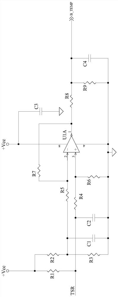
In addition, when converting and amplifying the detection data of the thermistor, the component differences in the amplifying circuit and the error of the power supply voltage will also cause the output value to deviate from the actual value, which will lead to inaccurate temperature detection standards and affect the upper limit of the nozzle’s operating temperature. setting, the reliable operation of the nozzle cannot be guaranteed

Method used


Image

  • Temperature calibration system and method for printer nozzle
  • Temperature calibration system and method for printer nozzle

Examples


Embodiment Construction

[0017] The present invention will be further described in detail below in conjunction with the accompanying drawings and embodiments.

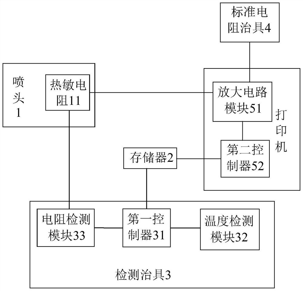
[0018] Such as figure 1 As shown, the printer nozzle temperature calibration system in this embodiment includes a nozzle 1, a memory 2, an amplifier circuit module 51, a second controller 52, a detection fixture 3, and a standard resistance fixture 4 with a known resistance value.

[0019] Wherein the nozzle 1 is provided with a thermistor 11 for detecting the temperature of the nozzle 1. The setting method of the thermistor 11 is set according to specific needs. The thermistor 11 is used to detect the real-time temperature of the nozzle 1 when it is working, thereby preventing the nozzle 1 The temperature is too high and the nozzle 1 is damaged. The resistance value of the thermistor 11 will change with the change of the temperature of the shower head 1 . The resistance-temperature relationship of the thermistor 11 is determined according t...


PUM


Abstract

The invention relates to a temperature calibration system for a printer nozzle. The system comprises a detection jig, a nozzle body and a memory, wherein the nozzle body and the memory are arranged ina printer, a thermistor is arranged on the nozzle body, the detection jig comprises a first controller, a temperature detection module for detecting an ambient temperature, and a resistance detectionmodule for detecting a resistance value, the resistance detection module can be electrically connected with the thermistor, and the temperature detection module and the resistance detection module are electrically connected with the first controller separately. The invention also relates to a temperature calibration method for the printer nozzle, which is characterized in that the nozzle body isenabled to be electrically connected with the detection jig, and a resistance and a temperature of the thermistor on the nozzle body are calibrated; and the nozzle body is installed in the printer ina working process, a resistance value R of the thermistor is acquired in real time, and a real-time nozzle temperature T is calculated according to a resistance-temperature relation corresponding to athermistor material, a calibration resistance R0 and a calibration temperature T0. According to the temperature calibration system and method for the printer nozzle, errors can be eliminated, and thedetection temperature can be calibrated.

Description

technical field [0001] The invention relates to a temperature calibration system for a printer nozzle, and also relates to a temperature calibration method for a printer nozzle. Background technique [0002] In the inkjet printing technology, the ink needs to be heated to effectively realize the ink output and achieve a good printing effect. In the existing technology, after the ink enters the nozzle, the nozzle is directly heated by the heating device, and the temperature of the ink rises instantaneously. Further, air bubbles are generated to realize the output printing of ink droplets. However, if the temperature of the nozzle is too high, it will damage the nozzle. Therefore, a high temperature threshold is usually set during the printing process. When the temperature of the nozzle reaches the high temperature threshold, the heating of the nozzle is stopped, and the printing work is stopped at the same time, so as to cool down the nozzle. After dropping to the set temper...

Claims


Application Information

Patent Timeline
Patent Type & Authority Applications(China)
IPC IPC(8): B41J2/14B41J2/11B41J29/393
CPCB41J2/11B41J2/14112B41J2/14153B41J29/393
Inventor 张祖昆汪一舟竺宗光
Owner NINGBO DELI KEBEI TECH CO LTD
Learn More