Eureka AIR delivers breakthrough ideas for toughest innovation challenges, trusted by R&D personnel around the world.

Propelling device for self-propelled tunnel boring machine

A propulsion device, self-propelled technology, applied in tunnels, mining equipment, earth-moving drilling, etc., can solve the problems of high manufacturing cost, lag in support, and inability to achieve support and spray anchors.

Pending Publication Date: 2020-12-22
中船重工(青岛)轨道交通装备有限公司
View PDF0 Cites 0 Cited by
  • Summary
  • Abstract
  • Description
  • Claims
  • Application Information

AI Technical Summary

Problems solved by technology

Although the single-shield mode shortens the length of the main engine, it needs the assistance of segments to advance forward, and it is impossible to realize the support spray anchor
[0003] The propulsion cylinder in double shield mode can achieve safe propulsion under the protection of the shield, but the structure is complicated, and it is difficult to realize the transition and disassembly
The open mode has flexibility, but the main engine is long and difficult to achieve small turns, the safety is poor, and it is difficult to disassemble and transfer. Common roadway boring machines include rock drills, double shield type, and open type
Double-shield mode propulsion cylinders can achieve safe propulsion under the protection of shields, but the structure is complex, it is difficult to dismantle the machine in transition, the cost of remanufacturing in transition is high, the safety of transition is poor, and the roadway is more sensitive to dust and gas. , is not easy to fire, and it is more difficult to disassemble the shield
The rock drill is more flexible to the section of the roadway, including horseshoe shape and rounded rectangle, but the driving efficiency is low, the safety is poor, and the support lags behind

Method used


Image

  • Propelling device for self-propelled tunnel boring machine
  • Propelling device for self-propelled tunnel boring machine
  • Propelling device for self-propelled tunnel boring machine

Examples


Embodiment Construction

[0014] The present invention will be further described below in conjunction with specific embodiments, and the advantages and characteristics of the present invention will become clearer along with the description. However, these embodiments are only exemplary and do not constitute any limitation to the scope of the present invention. Those skilled in the art should understand that the details and forms of the technical solutions of the present invention can be modified or replaced without departing from the spirit and scope of the present invention, but these modifications and replacements all fall within the protection scope of the present invention.

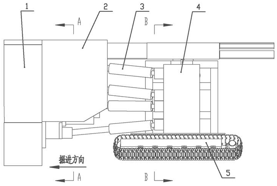
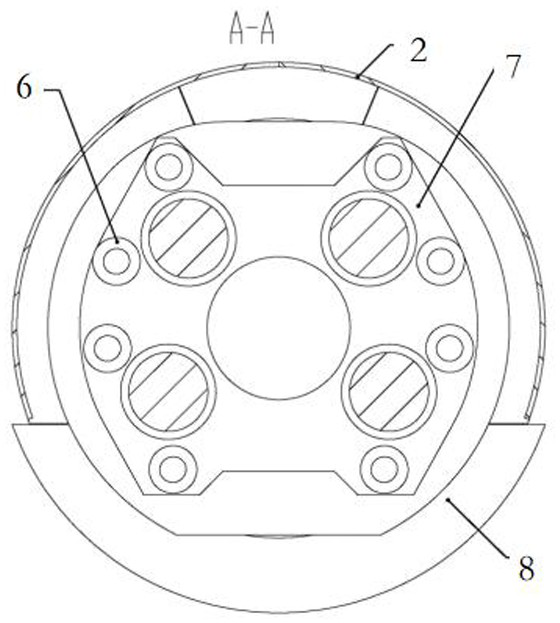
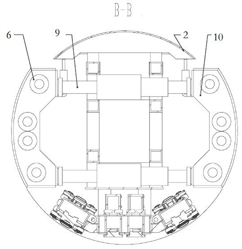
[0015] see Figure 1 to Figure 5 , the present invention relates to a propulsion device for a self-propelled roadway boring machine, comprising a self-propelled chassis main body 5, on which an upper support shoe cylinder unit and a lower part arranged parallel to the upper support shoe cylinder unit are installed. The stretc...


PUM


Abstract

The invention relates to a propelling device for a self-propelled tunnel boring machine. The propelling device comprises a self-propelled base plate body, and an upper supporting shoe oil cylinder unit and a lower supporting shoe oil cylinder unit in parallel with the upper supporting shoe oil cylinder unit are installed on the self-propelled base plate body. Supporting shoes are installed on theupper supporting shoe oil cylinder unit and the lower supporting shoe oil cylinder unit, and the supporting shoes on the two sides are symmetrically arranged along the self-propelled base plate body.A telescopic shield and a front shield are sequentially installed on the front part of the self-propelled base plate body, a driving system is installed on the telescopic shield, and a propelling unitis installed between the driving system and supporting shoes on the two sides of the self-propelled base plate body. The propelling device for the self-propelled tunnel boring machine has the advantages that the high tunneling speed can be achieved, an operator is safe away from a working face, the propelling device for the self-propelled tunnel boring machine can adapt to various geologies, thethrust of n oil cylinder is large, and the requirement for low-cost safe and rapid transition can be met through small-range disassembly.

Description

technical field [0001] The invention relates to a propulsion device for a self-propelled tunnel boring machine. Background technique [0002] Coal mine roadway boring machine is used for tunneling of coal mine roadway, the requirement is that the hole diameter is small (below 5m) and the host equipment should be shortened as much as possible to achieve a smaller turning radius. The roadways are of different lengths and require frequent transitions. The most common arrangement of main engine propulsion cylinders for existing roadheaders includes double-shield mode, single-shield mode, and open mode. Although the single-shield mode can shorten the length of the main engine, it needs the assistance of the segment to advance forward, and it cannot realize the support spray anchor. [0003] The dual shield mode propulsion cylinder can achieve safe propulsion under the protection of the shield, but the structure is complicated, and it is difficult to disassemble the machine in tr...

Claims


Application Information

Patent Timeline
IPC IPC(8): E21D9/06E21D9/093
CPCE21D9/06E21D9/0621E21D9/093
Inventor 樊治国郭志丁绍军韩丽森刘丽欢韩凝远王以栋刘桂涛
Owner 中船重工(青岛)轨道交通装备有限公司
Why Eureka
Eureka Blog
Learn More