
Anti-snow-accumulation power distribution cabinet

A power distribution cabinet, anti-snow technology, applied in the substation/power distribution device shell, electrical components, electromechanical devices, etc., can solve problems such as leakage short circuit, damage to electrical components, no snow removal device, etc., to achieve efficient use and liberate labor Effect

Active Publication Date: 2020-12-22
淮安市虎诚电气有限公司
View PDF5 Cites 1 Cited by
  • Summary
  • Abstract
  • Description
  • Claims
  • Application Information

AI Technical Summary

Problems solved by technology

[0002] In traditional power distribution cabinets, there is generally no snow removal device. As a result, on some outdoor power distribution cabinets, the snow is very thick after falling. When the weather turns fine, the snow melts, and the melted snow water enters the electrical cabinet along the Inside the cabinet, it will cause damage to electrical components, and may cause leakage and short circuit. The traditional power distribution cabinet, because of work needs, needs to be installed inside the power distribution cabinet. Ventilation fans are used to exchange the air inside the power distribution cabinet. and play a role in cooling the components

Method used


Image

  • Anti-snow-accumulation power distribution cabinet
  • Anti-snow-accumulation power distribution cabinet
  • Anti-snow-accumulation power distribution cabinet

Examples


Embodiment

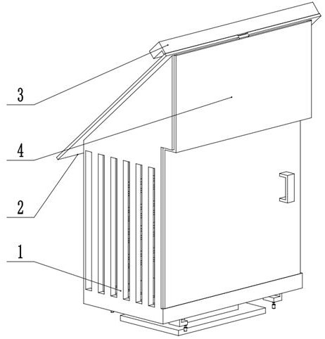
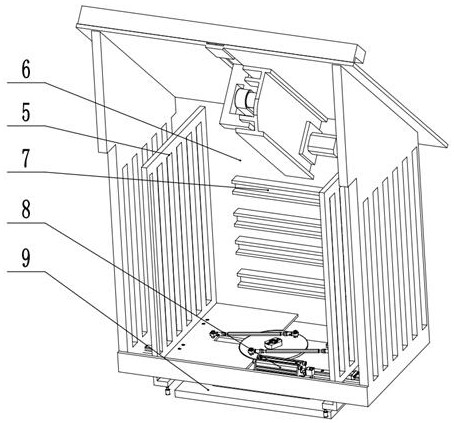
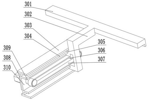
[0023] Embodiment: A kind of anti-snow power distribution cabinet, including electric cabinet side frame 1, electric cabinet top cover 2, electric cabinet door 4, electric cabinet inner frame 5, electric cabinet rear cover 6, electrical component seat 7, inner frame moving Device 8, electric cabinet base 9, electric cabinet side frame 1, electric cabinet upper cover 2, electric cabinet snow plowing device 3, electric cabinet door 4, electric cabinet inner frame 5, electric cabinet rear cover 6 are installed on fastening screws 809 The electric cabinet snow removal device 3 is installed on the lower side of the upper cover 2 of the electric cabinet, so that the snow brush unit 301 moves up and down on the upper surface of the upper cover 2 of the electric cabinet, and the electrical component seat 7 is relatively installed on the back cover 6 of the electric cabinet. Inside, the inside frame moving device 8 drives the inside frame 5 of the electric cabinet on both sides of the w...


PUM


Abstract

The invention discloses an anti-snow-accumulation power distribution cabinet, which comprises an electric cabinet side frame, an electric cabinet upper top cover, an electric cabinet door, an electriccabinet inner side frame, an electric cabinet rear cover, an electric appliance element seat, an inner side frame moving device and an electric cabinet base, and the electric cabinet side frame, theelectric cabinet upper top cover, an electric cabinet snow sweeping device, the electric cabinet door, the electric cabinet inner side frame and the electric cabinet rear cover are installed on fastening screws. the electric cabinet snow sweeping device is installed on the lower side of the electric cabinet upper top cover, so that the snow sweeping brush unit moves up and down on the upper surface of the electric cabinet upper top cover, the electric appliance element seat is oppositely installed on the inner side of the electric cabinet rear cover, and the inner side frame moving device drives the electric cabinet inner side frames on the two sides of the whole inner side to move as required to change the ventilation condition inside the power distribution cabinet. According to the invention, in the aspects of use, labor force can be saved for snow removal, the accident probability of the power distribution cabinet in the using process is reduced, snow removal work of the snow removal mechanism can be automatically adjusted according to the environment, the ventilation condition in the power distribution cabinet is changed, and the power distribution cabinet has dust removal, snow prevention and water prevention functions.

Description

technical field [0001] The invention relates to the field of mechanical structure design of a power distribution cabinet, in particular to a snow-prevention power distribution cabinet. Background technique [0002] In traditional power distribution cabinets, there is generally no snow removal device. As a result, on some outdoor power distribution cabinets, the snow is very thick after falling. When the weather turns fine, the snow melts, and the melted snow water enters the electrical cabinet along the Inside the cabinet, it will cause damage to electrical components, and may cause leakage and short circuit. The traditional power distribution cabinet, because of work needs, needs to be installed inside the power distribution cabinet. Ventilation fans are used to exchange the air inside the power distribution cabinet. And play the role of cooling components. Contents of the invention [0003] In view of the above problems, the present invention provides a snow-prevention ...

Claims


Application Information

Patent Timeline
IPC IPC(8): H02B1/28H02B1/30H02B1/56B08B1/00H02K7/10H02K7/06
CPCH02B1/28H02B1/306H02B1/565H02K7/1004H02K7/06B08B1/30B08B1/12
Inventor 雷磊
Owner 淮安市虎诚电气有限公司
Features
  • Generate Ideas
  • Intellectual Property
  • Life Sciences
  • Materials
  • Tech Scout
  • Unparalleled Data Quality
  • Higher Quality Content
  • 60% Fewer Hallucinations
Learn More