In-vitro centrifugal magnetic suspension artificial heart pump and using method

An artificial heart and magnetic levitation technology, applied in the field of medical devices, can solve problems such as insufficient stability, blood cell damage, and inability to output pulsatile blood flow, and achieve the effect of reducing rapid changes and speed changes, and reducing damage.

Active Publication Date: 2020-12-25
SHANDONG UNIV
View PDF7 Cites 3 Cited by
  • Summary
  • Abstract
  • Description
  • Claims
  • Application Information

AI Technical Summary

Problems solved by technology

(1) At present, there are no mature extracorporeal centrifugal artificial heart pump products in China and power blood pumps used with membrane lungs as ECMO. Most of the existing imported ECMO blood pumps use magnetic coupling drive mode, which is prone to rotation speed. The problem of loss, and this driving method is easy to cause hemolysis and thrombus due to the existence of the bearing structure
(2) Since the pump head and the drive motor are separated in the external centrifugal artificial heart, collisions between the impeller and the volute are prone to occur when the pump head is transported, which may cause scratches on the impeller and volute to increase the probability of hemolysis and thrombus
(3) The original pulsating blood flow, the placement angle of the blood pump, the vibration during operation and handling will all affect the operation stability of the impeller, causing the vibration of the impeller to cause the internal flow field of the blood pump to be disordered and aggravate the damage to blood cells. Serious complications that even lead to blood pump stalling
(4) The single-degree-of-freedom magnetic levitation structure has insufficient stability when the impeller rotates at high speed, and cannot output pulsating blood flow under simulated physiological conditions. The existing method of simulating pulsating blood flow by simply changing the impeller speed will aggravate blood cell damage

Method used


Image

  • In-vitro centrifugal magnetic suspension artificial heart pump and using method
  • In-vitro centrifugal magnetic suspension artificial heart pump and using method
  • In-vitro centrifugal magnetic suspension artificial heart pump and using method

Examples


Embodiment Construction

[0031] It should be noted that the following detailed description is exemplary and intended to provide further explanation of the present disclosure. Unless defined otherwise, all technical and scientific terms used in this disclosure have the same meaning as commonly understood by one of ordinary skill in the art to which this disclosure belongs.

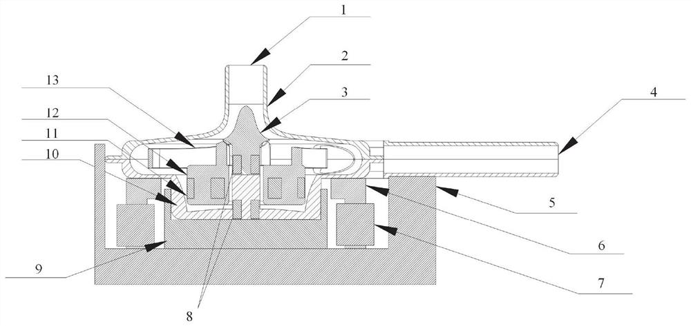
[0032] Such as figure 1Shown is a schematic structural diagram of an extracorporeal centrifugal magnetic levitation artificial heart pump provided by an embodiment of the present disclosure. The artificial heart pump mainly includes three parts: a centrifugal impeller, an upper cover plate 2 , a lower cover plate 10 and a drive control device. Wherein the upper cover plate 2 and the lower cover plate 10 form a volute structure, the centrifugal impeller is arranged in the volute space surrounded by the upper cover plate and the lower cover plate, the upper cover plate 2 is provided with a blood inlet channel 1 for the blood to flow ...


PUM


Abstract

The invention relates to an in-vitro centrifugal magnetic suspension artificial heart pump and a using method, and belongs to the technical field of medical instruments. The artificial heart pump comprises a shell structure; a blood inlet channel is formed in the top of the shell structure; a blood outlet channel is formed in the outer wall surface of the shell; a suspended and rotatable impellerbase is arranged in the centre of the interior of the shell; a flow guide cone is arranged at the position, below the blood outlet channel, of the interior of the shell; several permanent magnets areevenly arranged on the outer wall surface of the impeller base in the circumferential direction; several stator iron cores connected with the shell are evenly arranged at the bottom of the shell in the circumferential direction; and coils are arranged on the stator iron cores. The artificial heart pump disclosed by the invention is beneficial to reducing hemolysis and thrombus and can simulate andoutput pulsating blood flow.

Description

technical field [0001] The disclosure belongs to the technical field of medical devices, and in particular relates to an extracorporeal centrifugal magnetic levitation artificial heart pump and a use method thereof. Background technique [0002] The statements herein merely provide background information related to the present disclosure and do not necessarily constitute prior art. [0003] At present, the number of patients with heart failure in my country is increasing year by year. Heart transplantation is considered to be an effective method for the treatment of heart failure. However, the number of heart donors is very limited, which prevents this method from being widely used. The artificial heart pump is a device that provides power for human blood circulation through mechanical circulation. It can not only help patients safely transition to heart transplantation or recover heart function in the short term, but also replace heart transplantation for long-term circulat...

Claims


Application Information

Patent Timeline
Patent Type & Authority Applications(China)
IPC IPC(8): A61M1/10
Inventor 李东海刘泽辉张松李剑峰满佳
Owner SHANDONG UNIV
Why Eureka
Try Eureka