Centrifugal Pump

a centrifugal pump and centrifugal pump technology, applied in the direction of piston pumps, positive displacement liquid engines, liquid fuel engines, etc., can solve the problems of large size of centrifugal pump, waste of electrical energy, and inability to be easily portabl

Active Publication Date: 2009-12-24
BOARD OF RGT THE UNIV OF TEXAS SYST
View PDF31 Cites 20 Cited by
  • Summary
  • Abstract
  • Description
  • Claims
  • Application Information

AI Technical Summary

Problems solved by technology

Existing centrifugal blood pumps are large and waste electrical energy.
Accordingly, they are not well suited for portable use.
E

Method used


Image

  • Centrifugal Pump
  • Centrifugal Pump
  • Centrifugal Pump

Examples


Embodiment Construction

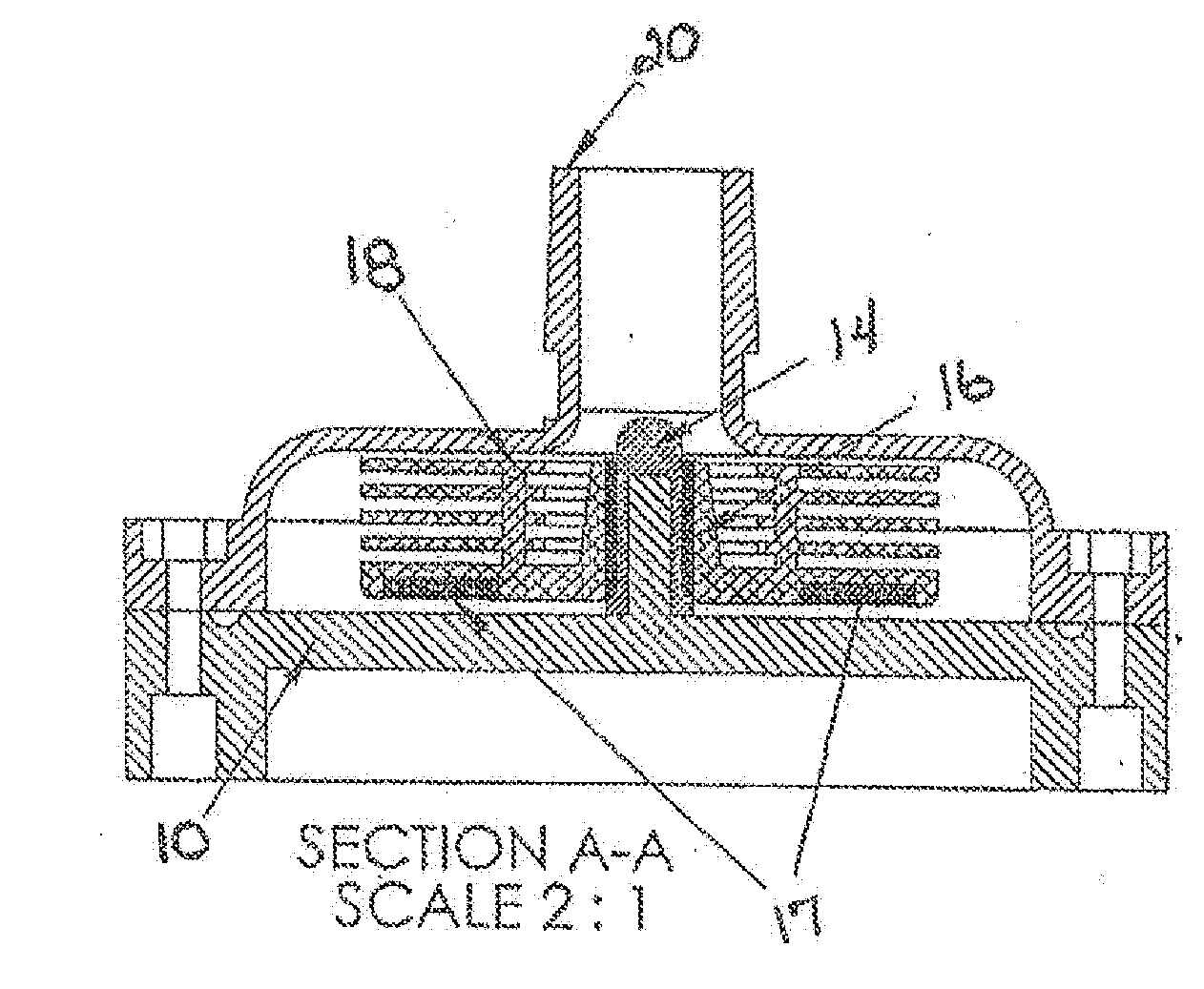
[0027]A preferred embodiment of the invention is directed to a Tesla centrifugal pump for pumping biocompatible fluids, such a blood. In one preferred embodiment, the pump is made from biocompatible materials, thereby making it suitable for implantation in a patient, including in a human patient. In another preferred embodiment, the pump is made from non-biocompatible materials and coated with a biocompatible material coating. The Tesla design was chosen because it creates less turbulence and is less susceptible to cavitation than traditional bladed centrifugal pumps. Therefore, the Tesla design should produce less hemolysis. Additionally, the bladeless geometry of the Tesla impeller allows the design to be scaled down in size while less susceptible to performance variability from the dominance of viscous forces at a small scale.

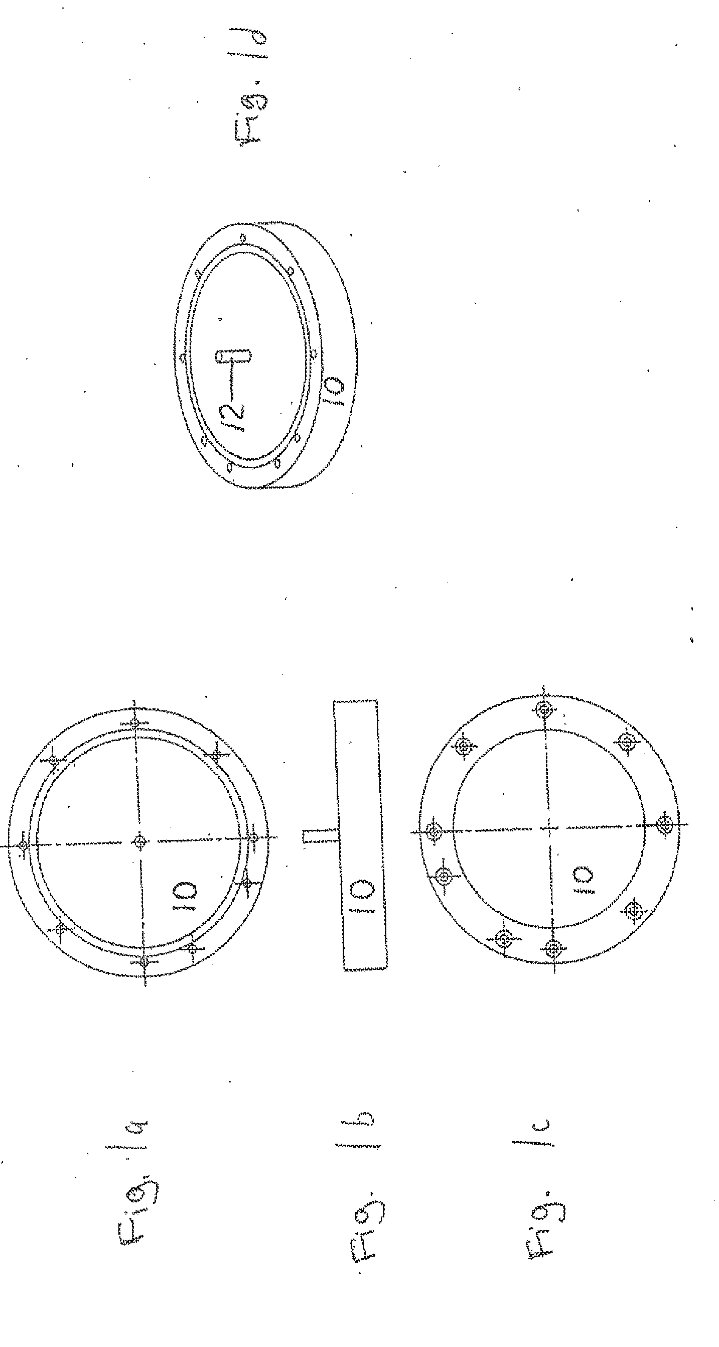
[0028]A preferred embodiment of the invention comprises a pump housing bottom 10, as shown in FIGS. 1a-1d, 7b and 9a. In a preferred embodiment, the pump ho...


PUM


Abstract

The invention is directed to a multi-disk centrifugal pump suitable for pumping fluids, including biocompatible fluids, such as blood. The design of the pump components is optimized to reduce or eliminate the probability of clotting and hemolysis when pumping blood, and to be energy efficient and resistant to physical shock for portable applications.

Description

PRIORITY INFORMATION[0001]This application claims the benefit of U.S. Provisional Application No. 61 / 074,053, filed on Jun. 19, 2008.GOVERNMENT RIGHTS[0002]This invention was made with United States Government support under Grant No. W81XWH-07-1-0496, awarded by the United States Army. The United States Government has certain rights in the invention.FIELD OF THE INVENTION[0003]The invention is directed to a multi-disk centrifugal pump suitable for pumping fluids, including biocompatible fluids, such as blood. The design of the pump components is optimized to reduce or eliminate the probability of clotting and hemolysis when pumping blood, and to be energy efficient and resistant to physical shock for portable applications.BACKGROUND OF THE INVENTION[0004]Existing centrifugal blood pumps are large and waste electrical energy. Accordingly, they are not well suited for portable use. Existing ventricular assist devices (“VADs”) do not scale down in size so that they can not be used in t...

Claims


Application Information

Patent Timeline
IPC IPC(8): F04D13/06F04D29/42F04D29/22A61M60/178A61M60/232A61M60/422A61M60/818
CPCA61M1/101A61M1/1036F04D29/048F04D5/001A61M60/824A61M60/419A61M60/148A61M60/232A61M60/422A61M60/178A61M60/818
Inventor GILL, BRIJESHCOX, JR., CHARLES S.AROOM, KEVIN R.
Owner BOARD OF RGT THE UNIV OF TEXAS SYST
Why Eureka
Try Eureka