
Cleaning device for filter cloth of filter press

A technology for cleaning devices and filter presses, which is applied in the direction of filtration separation, separation methods, chemical instruments and methods, etc., and can solve the problems of inability to ensure stable performance of filter presses, unreasonable cleaning structure design, and reduced working efficiency of filter presses. and other problems, to achieve the effect of long-term stability of filtration performance, improvement of cleaning effect, and high degree of automation

Pending Publication Date: 2020-12-25
青岛时代新环境科技有限公司
View PDF11 Cites 0 Cited by
  • Summary
  • Abstract
  • Description
  • Claims
  • Application Information

AI Technical Summary

Problems solved by technology

Therefore, the performance of the filter cloth directly affects the filter press effect of the filter press, and the contact between the filter cloth and the material, incomplete unloading and insufficient cleaning of the filter cloth will cause the performance of the filter cloth to attenuate
[0003] However, the existing filter press usually does not have a special filter cloth cleaning system. When cleaning the filter cloth, the filter cloth needs to be removed and then cleaned, which leads to extremely low cleaning efficiency, which seriously reduces the work of the filter press. efficiency
In addition, for some high-end filter presses, although an automatic filter cloth cleaning system is designed, its cleaning structure is not designed reasonably, resulting in poor cleaning effect and high failure rate. It takes a long time to clean the filter cloth and cannot be used normally. Stable filtration performance

Method used


Image

  • Cleaning device for filter cloth of filter press
  • Cleaning device for filter cloth of filter press
  • Cleaning device for filter cloth of filter press

Examples


Embodiment Construction

[0024] The present invention is introduced below by accompanying drawing.

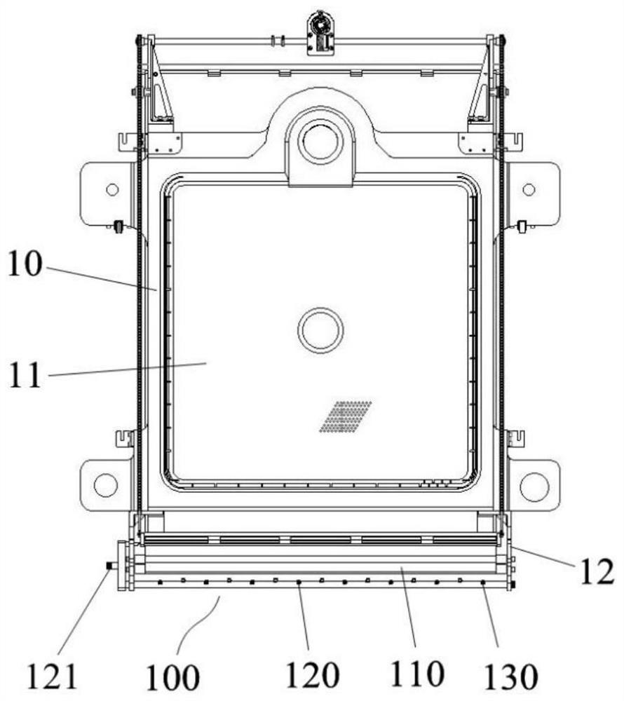
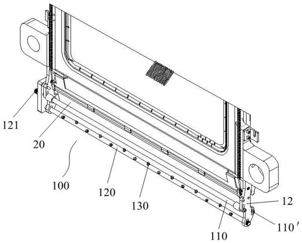
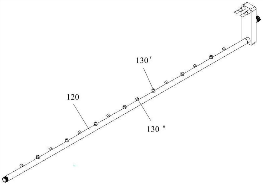
[0025] figure 1 The structure of a cleaning device 100 for a filter cloth of a filter press according to the present invention is shown. The filter press includes a plurality of filter plate units 10 . Such as figure 1 As shown, the filter plate unit 10 includes a filter plate 11 . The cleaning device 100 includes a mounting frame 12 disposed on the lower end of the filter plate 11 . The filter plate unit 10 also includes a filter cloth 20 arranged between adjacent filter plates 11, and two filter cloths 20 are arranged in a cavity formed after two adjacent filter plates 11 are combined. It is enclosed in the frame around the filter plate 11. The material to be filtered enters between the two filter cloths 20 through the feeder between the two filter cloths 20, and under the pressure filtration action of the filter plate 11 of the filter press, the solid material is intercepted by the filter cloth...


PUM

PropertyMeasurementUnit
angleaaaaaaaaaa

Abstract

According to the cleaning device for the filter cloth of the filter press, the filter press comprises a plurality of filter plates and the filter cloth, a mounting frame is fixed to the lower ends ofthe filter plates, the filter cloth is arranged to move relative to the filter plates, and the cleaning device comprises two flattening positioning shafts which are mounted on the mounting frame in astaggered and parallel mode; the filter cloth on the two sides of the filter plate respectively bypasses the corresponding flattening positioning shafts and can move around the flattening positioningshafts; the cleaning water pipe is arranged below the two flattening positioning shafts, is mounted on the mounting frame and is parallel to the two flattening positioning shafts; the plurality of cleaning spray heads are uniformly arranged on the cleaning water pipe at intervals along the axial direction; the plurality of cleaning spray heads are sequentially and alternately aligned with the twoflattening positioning shafts respectively; wherein the two flattening positioning shafts are configured to enable the filter cloth to be kept centered and flattened in the moving process of the filter cloth, and cleaning liquid is sprayed to the area, surrounding the flattening positioning shafts, of the filter cloth through the cleaning spray heads, so that the filter cloth is cleaned.

Description

technical field [0001] The invention relates to the technical field of solid-liquid separation, in particular to a filter press, in particular to a cleaning device for filter cloth of a filter press. Background technique [0002] The filter press is used for solid-liquid separation of sludge. In order to ensure the working efficiency and effect of the filter press, the filter cloth of the filter press must be cleaned in a timely and effective manner. The filter press relies on pressurizing the material in the closed cavity to force the liquid in the material to pass through the filter cloth to achieve the purpose of solid-liquid separation. Therefore, the performance of the filter cloth directly affects the filter press effect of the filter press, and the contact between the filter cloth and the material, incomplete unloading and insufficient cleaning of the filter cloth will cause the performance of the filter cloth to attenuate. [0003] However, the existing filter press...

Claims


Application Information

Patent Timeline
Patent Type & Authority Applications(China)
IPC IPC(8): B01D25/32B01D25/34
CPCB01D25/32B01D25/346
Inventor 陈传好王涛王萍王媚杨英英潘震任升郑玉丽
Owner 青岛时代新环境科技有限公司
Learn More