Cylinder cover blocking die structure

A mold and block technology, which is applied in the field of cylinder head block mold structure, can solve the problems of inapplicability of molds of different specifications, inconvenient splicing and installation, waste of transmission force, etc., to facilitate splicing, two-way linkage mold closing, and improve practicality. sexual effect

CN112122534APending Publication Date: 2020-12-25江苏南洋中京科技有限公司
0 Cites 0 Cited by

Patent Information

Authority / Receiving Office
CN · China
Patent Type
Applications(China)
Current Assignee / Owner
Publication Date
2020-12-25

Smart Images

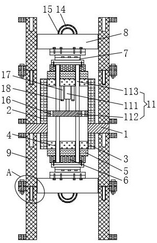
  • Figure 1
    Figure 1
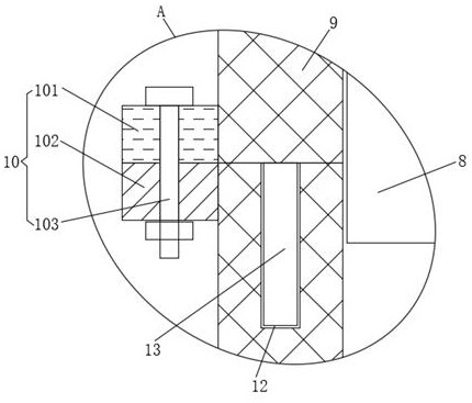
  • Figure 2
    Figure 2
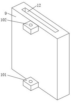
  • Figure 3
    Figure 3
Patent Text Reader

Abstract

The invention discloses a cylinder cover blocking mold structure. The cylinder cover blocking die structure comprises fixing plates, wherein a first fixing frame is fixedly connected to the tops of the fixing plates, a second fixing frame is fixedly connected to the bottoms of the fixing plates, and bottom plates are fixedly connected to the top of the inner side of the first fixing frame and thebottom of the inner side of the second fixing frame; and a mounting pad is fixedly connected to the outer side of each bottom plate. According to the cylinder cover blocking die structure, splicing frames are convenient to splice and use through splicing mechanisms; meanwhile, movable die bases are driven by an up-down linkage mechanism to move up and down for bidirectional die assembly, so that the problems that an existing cylinder cover blocking die structure is inconvenient to splice and install and not suitable for dies of different specifications, the existing die structure is low in dieassembly efficiency and high in cost performance, two-way linkage and assembly of two dies can not be carried out simultaneously, and the transmission force is wasted are solved. The cylinder cover blocking die structure has the advantages of being convenient to splice and capable of achieving two-way linkage die assembly, and improving the die frame splicing efficiency and the die assembly efficiency.
Need to check novelty before this filing date? Find Prior Art

Description

technical field

[0001] The invention relates to the technical field of segment mold devices, in particular to a mold structure for a cylinder head block mold. Background technique

[0002] Occlusion forging means that in a closed cavity (made by clamping the upper mold and the lower mold), through the one-way or opposite movement of more than two molds or punches, the metal is extruded to fill the cavity, so as to obtain no flash The precision forging process technology of near-net size precision forgings. Different from ordinary closed die forging, closed forging not only needs to provide the compacting force for extrusion of the metal billet in the closed cavity, but also needs to provide the clamping force required for the upper and lower dies to be closed.

[0003] However, the existing mold structure of the cylinder head block mold is not convenient for splicing and installation, and is not suitable for molds of different specifications. At the same time, the existing ...

Examples

Embodiment Construction

[0022] The following will clearly and completely describe the technical solutions in the embodiments of the present invention with reference to the accompanying drawings in the embodiments of the present invention. Obviously, the described embodiments are only some, not all, embodiments of the present invention. Based on the embodiments of the present invention, all other embodiments obtained by persons of ordinary skill in the art without making creative efforts belong to the protection scope of the present invention.

[0023] see Figure 1-3 , a cylinder head block mold structure, including a fixed plate 1, the top of the fixed plate 1 is fixedly connected with a first fixed frame 2, the bottom of the fixed plate 1 is fixedly connected with a second fixed frame 3, the inside of the first fixed frame 2 The bottom of the top and the inner side of the second fixed frame 3 are fixedly connected with the base plate 4, because the bottom of the base plate 4 is fixedly connected wi...