Lifting and rotating device for automobile manufacturing and implementation method thereof

A technology of automobile manufacturing and rotating device, applied in the direction of lifting device, lifting frame, etc., can solve the problems of poor rotation stability and shorten the service life of hydraulic rod, and achieve the effect of prolonging the service life, improving the rotating stability and improving the stability of the device.

Inactive Publication Date: 2020-12-25
NANJING SHILAIER AUTOMOTIVE ELECTRONICS CO LTD
View PDF0 Cites 2 Cited by
  • Summary
  • Abstract
  • Description
  • Claims
  • Application Information

AI Technical Summary

Problems solved by technology

[0003] The prior art has the following problems: 1. The lifting operation of the existing car manufacturing lifting rotating device is mostly completed by the hydraulic rod, and the weight of the lift is suppressed on the hydraulic rod for a long time, which is easy to shorten the service life of the hydraulic rod; 2. The rotation operation of the lifting and rotating device used in automobile manufacturing is mostly completed by the rotating motor, and the rotation stability is poor

Method used


Image

  • Lifting and rotating device for automobile manufacturing and implementation method thereof
  • Lifting and rotating device for automobile manufacturing and implementation method thereof
  • Lifting and rotating device for automobile manufacturing and implementation method thereof

Examples


Embodiment 1

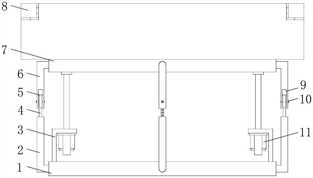
[0032] see Figure 1-8 , the present invention provides the following technical solutions: a lifting and rotating device for automobile manufacturing, including a base 1, first support plates 3 are connected to both sides above the base 1, and first support plates 3 are installed on the two first support plates 3. An electric cylinder 11, a lifting platform 7 is arranged above the base 1, the output shaft ends of the two first electric cylinders 11 are connected with the lifting platform 7, and several lower support rods 2 are evenly distributed on the outer edge of the base 1. The tops of the lower support rods 2 are all connected with extension rods 4, the outer edge of the lifting platform 7 and the positions corresponding to several lower support rods 2 are connected with upper support rods 6, and the bottom ends of several upper support rods 6 are all opened. There is a moving groove 9, and several extension rods 4 pass through the bottom ends of the corresponding upper s...

Embodiment 2

[0041] The difference of this embodiment compared with embodiment 1 is:

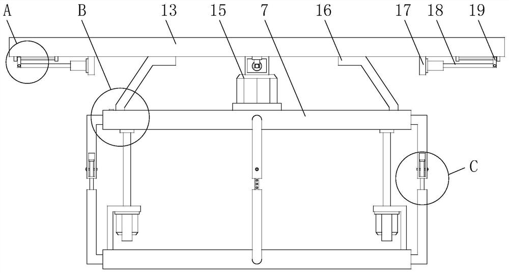
[0042] Specifically, both sides of the bottom end of the rotating table 8 are connected with auxiliary support frames 16, and the bottom ends of the two auxiliary support frames 16 are connected with rotating balls 22. Annular rotating groove 23,

[0043] By adopting the above technical solution, during the rotation of the rotating table 8 , the rotating ball 22 below the auxiliary support frame 16 rotates synchronously in the annular rotating groove 23 on the lifting table 7 , which can improve the rotation stability of the rotating table 8 .

[0044] Specifically, an oil injection channel is provided on one side of the lifting platform 7 and located at the annular rotating groove 23, the oil injecting channel and the annular rotating groove 23 are provided in a connected structure, and the top of the oil injecting channel is provided with a cork.

[0045] By adopting the above technical scheme, the oi...

Embodiment 3

[0048] The difference of this implementation compared with embodiment 1 and embodiment 2 is:

[0049] Specifically, the four sides of the rotary platform 8 are provided with installation grooves 14, and the insides of the four installation grooves 14 are all provided with extension platforms 13, and the four extension platforms 13 are connected to the corresponding installation grooves 14 through rotation shafts 12. The bottom of each extension platform 13 is connected with two fixed plates 21, and the polished rod 20 is connected between the two fixed plates 21. The polished rod 20 is slidably connected with a moving block 19, and the bottom four side walls of the rotary table 8 are connected with a second The supporting plate 17 and the four second supporting plates 17 are equipped with second electric cylinders 18 on one side close to the moving block 19 , and the output shafts of the four second electric cylinders 18 are hinged to the corresponding side moving block 19 .

...


PUM


Abstract

The invention discloses a lifting and rotating device for automobile manufacturing and belongs to the technical field of automobile manufacturing. The lifting and rotating device comprises a base, first supporting plates are connected to the two sides of the upper portion of the base correspondingly, first electric cylinders are installed on the two first supporting plates correspondingly, and a lifting table is arranged above the base. The output shaft ends of the two first electric cylinders are connected with the lifting table, a plurality of lower supporting rods are evenly distributed onthe circumference of the outer edge of the base, and the top ends of the multiple lower supporting rods are all connected with extending rods. The invention further discloses an implementation methodof the lifting and rotating device for automobile manufacturing. The lifting and rotating device is provided with the lower supporting rods, the extending rods, first bolt holes, upper supporting rods, moving grooves, second bolt holes, fastening bolts and limiting blocks, the structures are matched with one another, rising and falling of the lifting table are not affected, meanwhile the effect ofsupporting the lifting table can be achieved, and device stability is improved. In addition, the situation that the weight only presses on output shafts of the first electric cylinders can be avoided, and the service life of the first electric cylinders is prolonged.

Description

technical field [0001] The invention belongs to the technical field of automobile manufacturing, and in particular relates to a lifting and rotating device for automobile manufacturing and a realization method thereof. Background technique [0002] In recent years, with the rapid development of the country's economy, the number of road mileage has increased rapidly, and the use of automobiles has begun to show a rapid growth of geometric order. In automobile manufacturing, it is often necessary to use lifting and rotating devices. Although the existing automobile manufacturing uses lifting The production process of the rotary device is becoming more and more mature, but there are still some shortcomings to be improved. [0003] The prior art has the following problems: 1. The lifting operation of the existing car manufacturing lifting rotating device is mostly completed by the hydraulic rod, and the weight of the lift is suppressed on the hydraulic rod for a long time, which...

Claims


Application Information

Patent Timeline
Patent Type & Authority Applications(China)
IPC IPC(8): B66F7/06B66F7/28
CPCB66F7/06B66F7/28
Inventor 胡兵彭培石
Owner NANJING SHILAIER AUTOMOTIVE ELECTRONICS CO LTD
Why Eureka
Try Eureka