
A self-regulating temperature-compensated clamp

A technology of temperature compensation and self-regulation, which is applied in the direction of hose connection devices, mechanical equipment, pipes/pipe joints/fittings, etc. It can solve problems such as inability to achieve self-regulation, leakage, and increased hardness, and achieve the effect of shortening product life

Active Publication Date: 2022-04-01
DONGFENG COMML VEHICLE CO LTD
View PDF17 Cites 0 Cited by
  • Summary
  • Abstract
  • Description
  • Claims
  • Application Information

AI Technical Summary

Problems solved by technology

[0003] However, due to the material properties of the rubber hose, the sealing force fluctuates with temperature and decreases with stress relaxation. Therefore, once the clamp is tightened, its state is fixed. When the outside temperature drops to the stress relaxation of the rubber hose (stress relaxation: The force used to maintain the applied strain will decrease or even disappear with time) After the temperature is lowered, the sealing force value will gradually decay with the temperature decrease, especially below 0°C, the material elasticity will decay, the hardness will increase, and leakage will easily occur
[0004] Most of the existing elastic clamps use spring elasticity for compensation. For example, the Chinese utility model patent application with the authorized announcement number CN208845904U discloses a vacuum clamp with adjustable temperature compensation, including clamp I, clamp II, spring, lock Tightening mechanism and pre-tightening force adjustment mechanism, the pre-tightening force is adjusted through the adjusting part and the pre-tightening force is known through the pre-tightening force display mechanism, which overcomes the problem of pipe leakage caused by the deformation of the clamp caused by thermal expansion and contraction, but The pre-tightening force adjustment mechanism in this application needs to be manually adjusted and cannot be self-adjusted; another example is the Chinese invention patent application with the notification number CN108443611A, which discloses an elastic clamp assembly. The elastic clamp assembly includes a clamp body, For locking bolts, springs, hollow limit discs, limit posts and guide frames, this application uses spring elasticity for compensation, which can only compensate for the clamping force within a certain range, and long-term compensation for the clamping force will increase the stress of the rubber material Slack, shortening the product life of the rubber hose

Method used


Image

  • A self-regulating temperature-compensated clamp
  • A self-regulating temperature-compensated clamp
  • A self-regulating temperature-compensated clamp

Examples


Embodiment 1

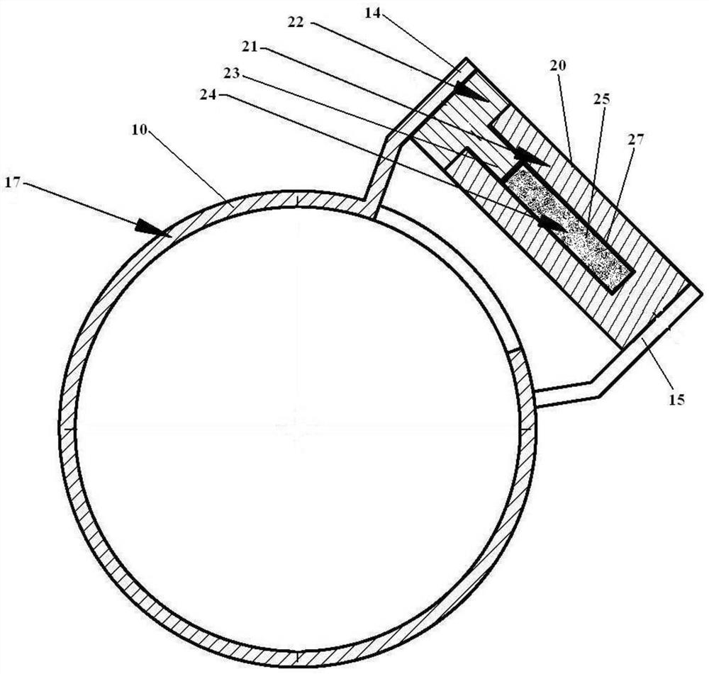
[0026] combine figure 1 As shown, a self-adjusting temperature compensation clamp includes an integrally formed elastic clamp band 17 and an expansion tube 20, the elastic clamp band 17 has a first connection end 14 and a second connection end 15, and the expansion tube 20 includes an outer One end of the outer cylinder 21 is closed and the other end is open. The outer cylinder 21 has a first cavity 23 and a second cavity 24 extending from the open end to the closed end along the axial direction of the outer cylinder 21. The first cavity 23 communicates with the second cavity 24, and the extending end of the lining core 22 extends into the first cavity 23 through the opening end of the outer cylinder 21, and the lining core 22 is slidingly connected with the inner wall of the outer cylinder 21. The protruding end of 22 abuts against the first connecting end 14 of the elastic clamp band 17, and the second cavity 23 is completely filled with an expansion medium 25. In this embod...

Embodiment 2

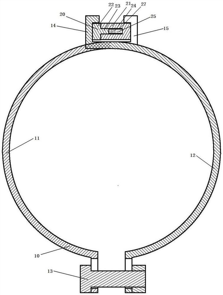
[0035] combine figure 2 As shown, a self-adjusting temperature-compensated clamp includes a clamp body 10 and an expansion tube 20. The clamp body 10 includes two semicircular clamps and a connecting piece 13. The two semicircular clamps are respectively left clamps 11 and the right clamp 12, the lower end of the left clamp 11 and the lower end of the right clamp 12 are connected by a connector 13, the connector 13 is a bolt in this embodiment, the upper end of the left clamp 11 is the second connection end 15, the right The upper end of the hoop is the first connecting end 14, the upper end of the left hoop 11 and the upper end of the right hoop 12 are arranged crosswise, and a reaction force structure is set, that is, when the two ends are close to each other, the inner diameter of the hoop body 10 increases, and the two ends are far away from each other. At this time, the inner diameter of the clamp body 10 decreases.

[0036] The expansion tube 20 is arranged between the...

Embodiment 3

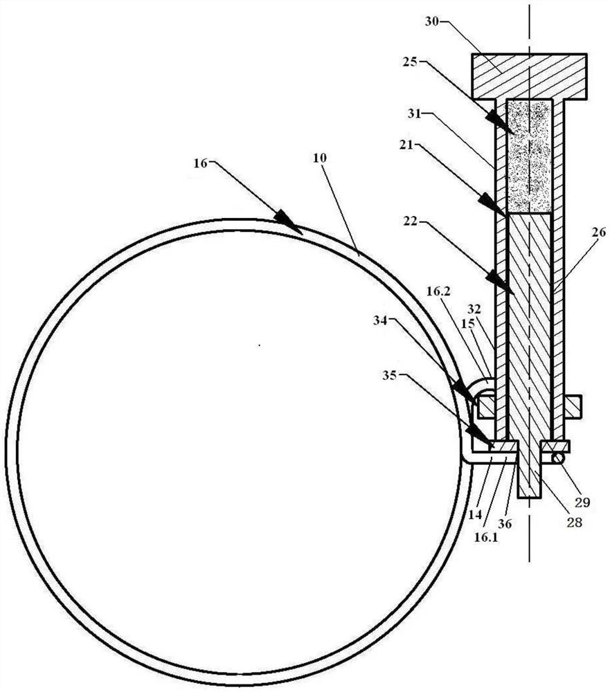
[0039] combine image 3 As shown, a self-adjusting temperature compensation clamp includes an integrally formed double steel wire snap ring 16, an expansion tube 20 and a locking member 30. The double steel wire snap ring 16 is a steel wire bent from the middle to form a double row of steel wires , one end of which includes two hook-shaped steel wire heads 16.2, and the other end includes an arc-shaped collar 16.1. The expansion tube 20 includes an outer cylinder 21 and a lining core 22. One end of the outer cylinder 21 is closed and the other end is open. The first cavity 23 and the second cavity 24 extending from the open end to the closed end in the axial direction of the outer cylinder, the first cavity 23 and the second cavity 24 communicate with each other, and the extending end of the lining core 22 passes through the outer cylinder 21 The opening end extends into the first cavity 23, the lining core 22 is slidingly connected with the inner wall of the outer cylinder 21...


PUM


Abstract

The invention relates to the field of connection devices, in particular to a self-adjusting temperature compensation clamp used for sealing rubber hoses. The self-adjusting temperature compensation clamp designed by the present invention includes a clamp body and an expansion tube for holding the pipe body tightly. The clamp body has a first connection end and a second connection end, and the first connection end and the second connection end intersect. Arranged and there is a distance between the first connection end and the second connection end; the expansion tube includes an outer cylinder and a lining core, one end of the outer cylinder is closed and the other end is open, and the outer cylinder has a first cavity and a second cavity, the second The first cavity communicates with the second cavity, the extending end of the lining core extends into the first cavity through the opening end of the outer cylinder, the lining core is slidingly connected with the inner wall of the outer cylinder, and the extending end of the lining core is connected with the clamp The first connecting end of the body is connected, the outer cylinder is connected to the second connecting end, and the second cavity is completely filled with expansion medium. The function of automatically adjusting the clamping force of the clamp at low temperature is realized by using the volume change of the expansion medium in different forms.

Description

technical field [0001] The invention relates to the field of connection devices, in particular to a self-adjusting temperature compensation clamp used for sealing rubber hoses. Background technique [0002] The application field of rubber hose covers various industrial manufacturing and circulation fields, and is usually responsible for the transmission of water, gas, oil and other media. The rubber hose relies on the clamping force to fit the tube body to the joint, which is the most common connection method. This method has a simple structure and low cost. [0003] However, due to the material properties of the rubber hose, the sealing force fluctuates with temperature and decreases with stress relaxation. Therefore, once the clamp is tightened, its state is fixed. When the outside temperature drops to the stress relaxation of the rubber hose (stress relaxation: The strength used to maintain the applied strain will decrease or even disappear with time) After the temperatu...

Claims


Application Information

Patent Timeline
Patent Type & Authority Patents(China)
IPC IPC(8): F16L33/03
CPCF16L33/03
Inventor 李箐张运东杨丹陶骏李鲲冯涛易俊霞马华跃
Owner DONGFENG COMML VEHICLE CO LTD
Learn More