Eureka AIR delivers breakthrough ideas for toughest innovation challenges, trusted by R&D personnel around the world.

Device for holding and lifting the reaction beam of the test bench

A test bench and crossbeam technology, which is applied in railway vehicle testing and other directions, can solve the problems that the crossbeam cannot be lifted and lowered independently, is inconvenient to disassemble and assemble the crossbeam, and has potential safety hazards, and achieves safe and reliable structural strength, wide application range, and shortened installation time. Effect

Active Publication Date: 2022-02-11
CRRC CHANGCHUN RAILWAY VEHICLES CO LTD
View PDF4 Cites 0 Cited by
  • Summary
  • Abstract
  • Description
  • Claims
  • Application Information

AI Technical Summary

Problems solved by technology

[0004] First of all, the crane is used to lift the counter force beam, the work efficiency is low, and there are potential safety hazards
[0005] Secondly, the front and rear clamping plates are used to fix the reaction force beam. The weight of the front and rear clamping plates is relatively large, about 453kg, and cannot be moved manually. There is a gantry frame above the clamping plate to hinder the lifting of the crane, which is not easy to disassemble and assemble the beam.
[0006] Furthermore, the beam cannot be lifted and lowered independently, and can only be lifted by means of a crane, which is inconvenient to use
[0007] Finally, adjusting the installation height of the beam by hoisting the crane is not only time-consuming, labor-intensive, low-precision, but also has potential safety hazards

Method used


Image

  • Device for holding and lifting the reaction beam of the test bench
  • Device for holding and lifting the reaction beam of the test bench
  • Device for holding and lifting the reaction beam of the test bench

Examples


Embodiment Construction

[0034] In order to enable those skilled in the art to better understand the solution of the present invention, the present invention will be further described in detail below in conjunction with the accompanying drawings and specific embodiments.

[0035] In this article, terms such as "upper, lower, left, right" are established based on the positional relationship shown in the drawings, and the corresponding positional relationship may also change accordingly depending on the drawings. It is understood as an absolute limitation on the scope of protection; moreover, relative terms such as "first" and "second" are only used to distinguish one from another component with the same name, and do not necessarily require or No such actual relationship or order between these components is implied.

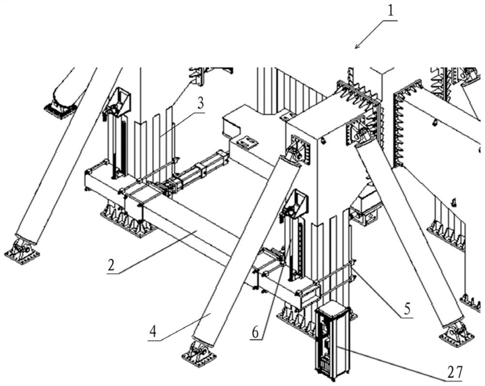
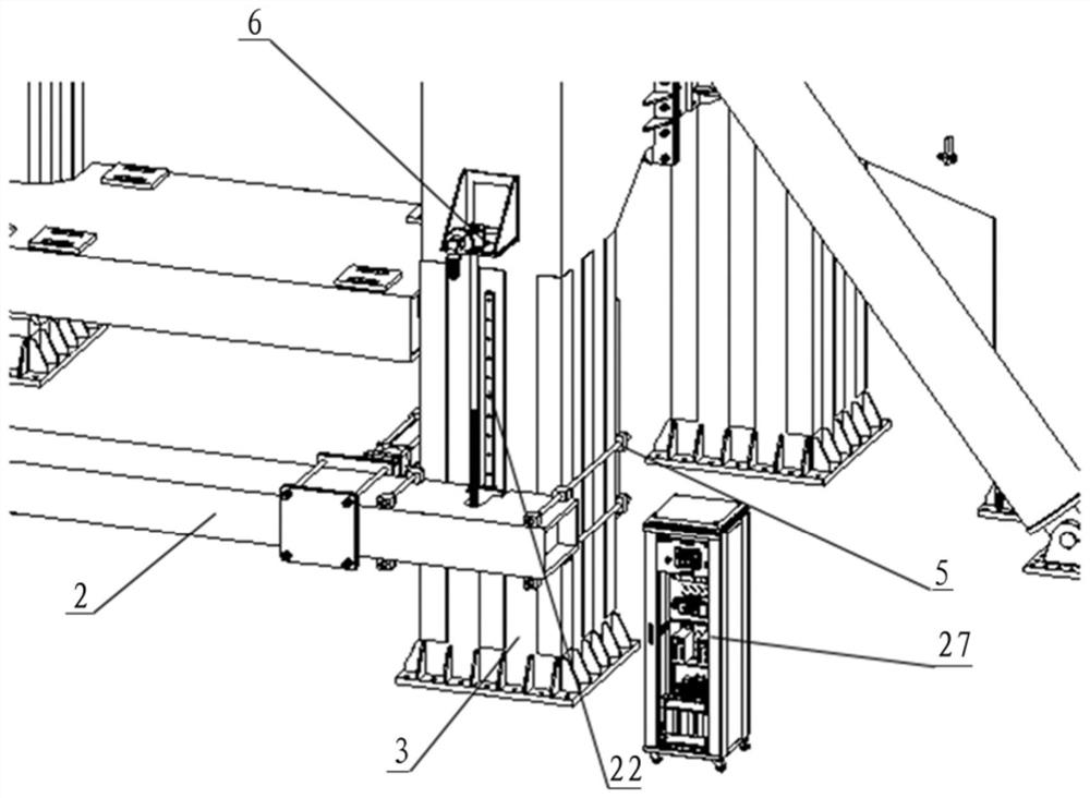
[0036] Please refer to figure 1 , figure 2 , figure 1 It is an axonometric view of a device for holding and lifting the reaction beam of the test bench disclosed in the embodiment of t...


PUM


Abstract

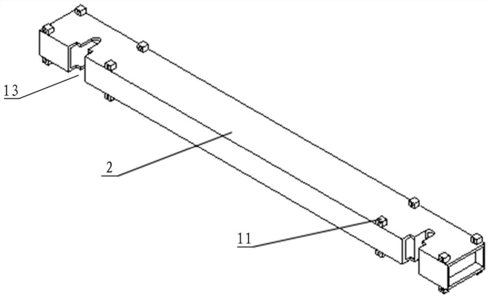
The invention discloses a device for holding and lifting a test bench reaction force beam, which comprises two columns (3) arranged at intervals and a reaction force beam (2) capable of moving up and down along the outer surface of the column (3) and positioned ), the two ends of the reaction force beam (2) are respectively provided with a holding mechanism (5) for fixing the reaction force beam (2) on the column (3), and the column (3) and the A drive mechanism (6) for driving the counter force beam (2) to rise or fall is provided between the counter force beams (2), and the side of the counter force beam (2) attached to the column (3) There are slot-shaped cutouts (13) for assembling the drive mechanism (6). The device has a simple structure, is safe and reliable, and is easy to disassemble and assemble. It can provide a great auxiliary effect for the vehicle or bogie test, can safely and effectively shorten the installation time, gain more test time for the test piece test, and significantly improve the test performance. efficiency.

Description

technical field [0001] The invention relates to the technical field of rail vehicle test devices, in particular to a device for lifting, lowering and fixing a test bench reaction beam in the design process of a rail vehicle. Background technique [0002] With the vigorous development of the rail transit industry, the vehicle design technology has been constantly innovating, and the continuous verification of the performance and reliability of the vehicle design has also continued to increase. Therefore, safe and reliable test equipment cannot be ignored. [0003] A typical test bench includes a reaction beam. During the test, the height of the reaction beam needs to be adjusted and fixed, but the existing equipment has the following disadvantages: [0004] First of all, using the crane to lift the counter force beam has low operating efficiency and potential safety hazards. [0005] Secondly, the front and rear clamping plates are used to fix the reaction force beam. The we...

Claims


Application Information

Patent Timeline
Patent Type & Authority Patents(China)
IPC IPC(8): G01M17/08
CPCG01M17/08
Inventor 王金田刘洪涛谭富星李永生
Owner CRRC CHANGCHUN RAILWAY VEHICLES CO LTD
Why Eureka
Eureka Blog
Learn More