
Anti-fire safety power distribution cabinet

A power distribution cabinet and safety technology, which is applied in the substation/power distribution device shell, electrical components, fire rescue, etc., can solve the problems of inability to automatically extinguish fire, poor heat dissipation, and inability to separate external power sources, so as to prevent further expansion of the fire Effect

Active Publication Date: 2020-12-25
湛江市志成电力有限公司
View PDF4 Cites 1 Cited by
  • Summary
  • Abstract
  • Description
  • Claims
  • Application Information

AI Technical Summary

Problems solved by technology

[0004] The invention proposes a fire-proof safety power distribution cabinet, which solves the problems of poor heat dissipation, inability to automatically extinguish fires, and inability to quickly separate from external power sources

Method used


Image

  • Anti-fire safety power distribution cabinet
  • Anti-fire safety power distribution cabinet
  • Anti-fire safety power distribution cabinet

Examples


Embodiment Construction

[0024] The following will clearly and completely describe the technical solutions in the embodiments of the present invention with reference to the accompanying drawings in the embodiments of the present invention. Obviously, the described embodiments are only some, not all, embodiments of the present invention.

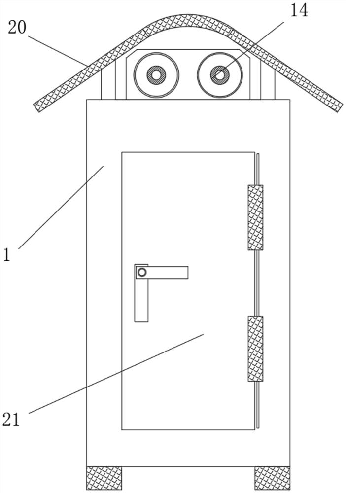
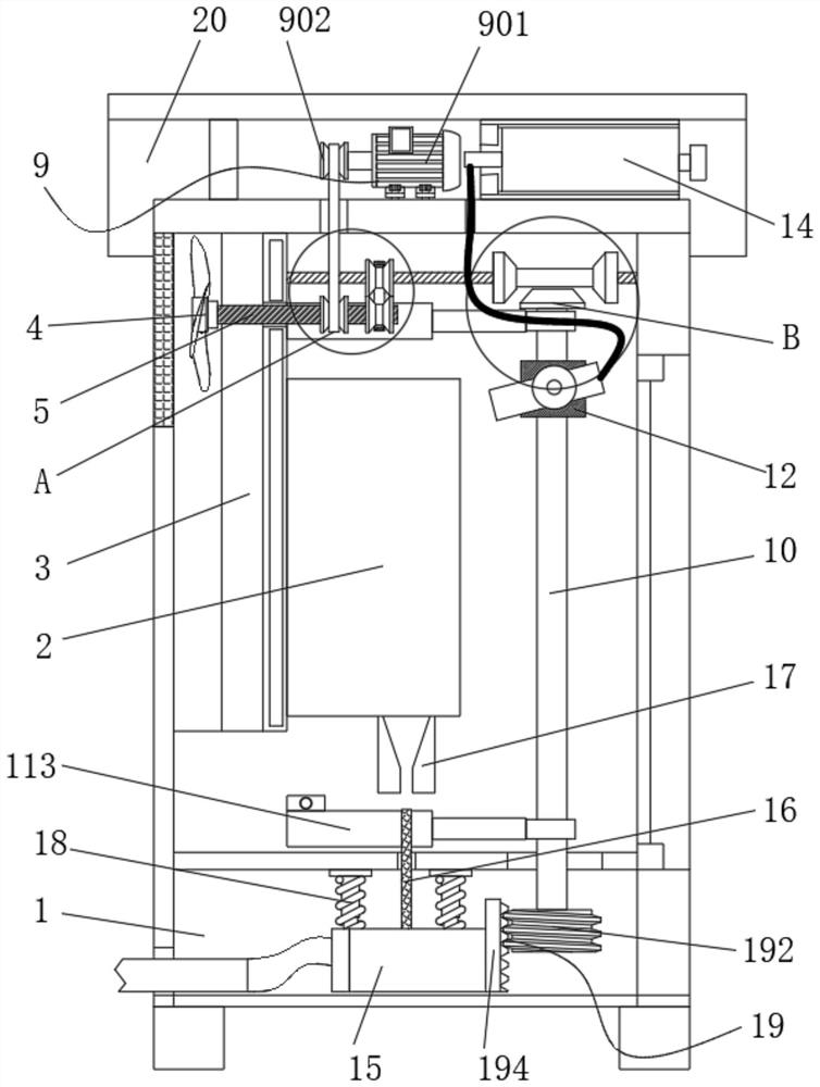
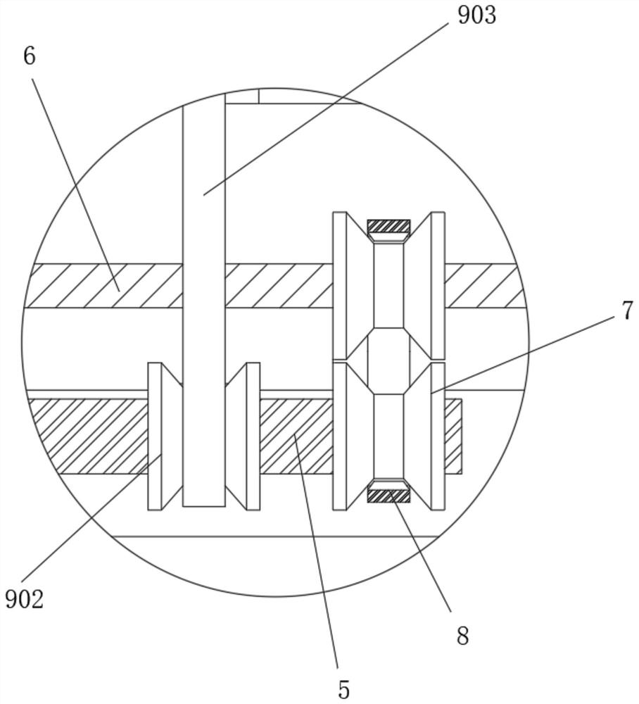
[0025] refer to Figure 1-6 , a fire-proof safety power distribution cabinet, comprising a cabinet body 1, a power distribution module 2 is arranged vertically inside the cabinet body 1, and a cooling block 3 is vertically fixedly connected to one side of the cabinet body 1, and the cooling block 3 The top center of the fan blade 4 is provided on the side far away from the power distribution module 2, and the center of the fan blade 4 runs through the inside of the cooling block 3 through the transmission rod 5, and both ends of the top side of the cooling block 3 far away from the fan blade 4 are horizontally connected There is a connecting rod 6, and the outer wall...


PUM


Abstract

The invention belongs to the technical field of power distribution cabinets, and particularly relates to an anti-fire safety power distribution cabinet. In order to solve the problems that an existingpower distribution cabinet is poor in heat dissipation effect, cannot extinguish a fire automatically and cannot be separated from an external power supply quickly, the following scheme is provided,namely, the anti-fire safety power distribution cabinet comprises a cabinet body, a power distribution module is vertically arranged in the cabinet body, a heat dissipation block is vertically and fixedly connected to one side of the cabinet body, fan blades are arranged on the side, away from the power distribution module, of the center of the top of the heat dissipation block, the centers of thefan blades penetrate through the heat dissipation block through transmission rods, connecting rods are horizontally and rotationally connected to the two ends of the side, away from the fan blades, of the top of the heat dissipation block, belt wheels are fixedly connected to the outer walls of the ends, close to each other, of the transmission rods and the connecting rods, the belt wheels are intransmission connection through a connecting belt, a power assembly is installed at the top of the cabinet body, and lead screws are vertically installed at the bottoms of the ends, away from the heat dissipation blocks, of the connecting rods. The cabinet has the advantages of being capable of efficiently dissipating heat, automatically extinguishing fire in time and quickly realizing separationfrom a power supply.

Description

technical field [0001] The invention relates to the technical field of power distribution cabinets, in particular to a fire-proof safety power distribution cabinet. Background technique [0002] In daily construction transportation and industrial production, a large number of power distribution cabinets are required to distribute the uniformly connected power in the grid to different electrical equipment through the power distribution cabinet, and then make the mechanical equipment perform various tasks. The structure of the power distribution cabinet generally includes a cabinet body and a power distribution module installed in the cabinet body. The installation and use of the power distribution cabinet needs to isolate the crowd to prevent interference. Causes of combustion, causing the flames to pass each other, causing more serious economic losses. [0003] At present, the structure of the power distribution cabinets on the market is too simple, and it cannot dissipate ...

Claims


Application Information

Patent Timeline
IPC IPC(8): H02B1/30H02B1/28H02B1/56A62C31/02A62C3/16
CPCH02B1/30H02B1/28H02B1/565A62C31/02A62C3/16
Inventor 徐克山
Owner 湛江市志成电力有限公司
Learn More