
Injection mold for plastic part production

A technology for injection molds and plastic parts, applied in the field of plastic parts production, can solve the problems of complicated steps, inconvenient overall disassembly, lack of rapid heat dissipation, etc., and achieves the effect of improving the heat dissipation coefficient and facilitating material retrieval.

Inactive Publication Date: 2020-12-29
吴保林
View PDF9 Cites 2 Cited by
  • Summary
  • Abstract
  • Description
  • Claims
  • Application Information

AI Technical Summary

Problems solved by technology

[0006] The purpose of the present invention is to provide an injection mold for the production of plastic parts to solve the inconvenience of dismantling the whole and complicated steps proposed in the above background technology; it does not have the function of preventing material adhesion; it does not have the effect of rapid heat dissipation, which affects solidification speed problem

Method used


Image

  • Injection mold for plastic part production
  • Injection mold for plastic part production
  • Injection mold for plastic part production

Examples


Embodiment Construction

[0030] The following will clearly and completely describe the technical solutions in the embodiments of the present invention with reference to the accompanying drawings in the embodiments of the present invention. Obviously, the described embodiments are only some, not all, embodiments of the present invention. Based on the embodiments of the present invention, all other embodiments obtained by persons of ordinary skill in the art without making creative efforts belong to the protection scope of the present invention.

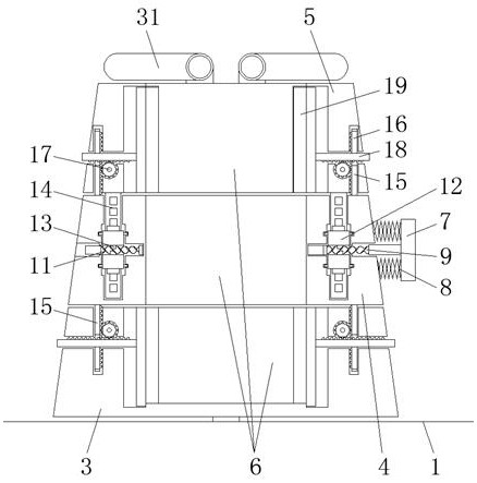
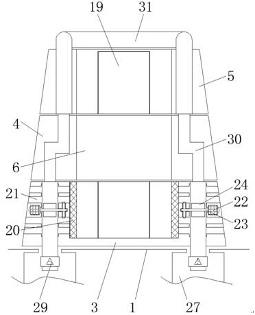
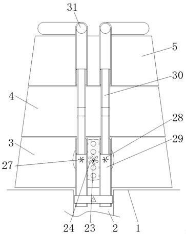
[0031] see Figure 1-7, the present invention provides a technical solution: an injection mold for the production of plastic parts, including a workbench 1, a water storage tank 2, a lower mold 3, a middle mold 4, an upper mold 5, an inner cavity 6, a pressing rod 7, a spring 8, First twist rod 9, fixed rod 10, second twist rod 11, connecting gear 12, bump 13, support block 14, guide rod 15, inner groove 16, sun gear 17, connecting rod 18, fixed plate 19, heat...


PUM


Abstract

The invention discloses an injection mold for plastic part production. The injection mold comprises a workbench, a lower mold, a middle mold, an upper mold and a motor, wherein a water storage tank isformed in the upper surface of the workbench, the lower mold is placed on the upper surface of the workbench, the upper surface of the lower mold is connected with the middle mold, the upper surfaceof the middle mold is connected with the upper mold, inner cavities are formed in the upper mold, the lower mold and the middle mold, a pressing rod penetrates through the surface of the right side ofthe middle mold, and the outer surface of the pressing rod is fixedly connected with a spring. According to the injection mold for plastic part production, the pressing rod can be pressed, so that afirst twisted rod slides through a fixing rod and a second twisted rod, the first twisted rod and the second twisted rod can extrude a convex block when sliding, so that the convex block drives a connecting gear to rotate to be meshed with a supporting block, the supporting block slides to jack up the upper mold and the middle mold, the upper mold, the middle mold and the lower mold are separated,the internal joints and the like can be cleaned conveniently, and meanwhile, materials can be taken conveniently.

Description

technical field [0001] The invention relates to the technical field related to the production of plastic parts, in particular to an injection mold for the production of plastic parts. Background technique [0002] Plastic parts are a kind of material that is mainly produced by resin as the main material and some additives are added. It can be seen everywhere in people's life. When producing plastic parts, an injection molding equipment is needed to pour the mold through the injection molding equipment. The material makes the material solidify according to the internal shape of the mold to achieve the effect of production, but the mold has some disadvantages: [0003] First, common injection molds are mainly divided into integrated molds and detachable molds. However, integrated molds are not easy to disassemble and clean, but the disassembly steps of detachable molds are complicated and inconvenient; [0004] Second, as mentioned above, the injection molding equipment pours...

Claims


Application Information

Patent Timeline
Patent Type & Authority Applications(China)
IPC IPC(8): B29C45/26B29C45/73B29C45/66B29C33/30
CPCB29C45/26B29C45/2606B29C45/73B29C45/66
Inventor 不公告发明人
Owner 吴保林
Learn More