
Vacuum filling machine convenient to overhaul

A filling machine and vacuum technology, which is applied in the field of vacuum filling machines, can solve the problems of leaking, troublesome and incapable of filling the hose, and achieve the effect of convenient and quick maintenance and improvement of efficiency.

Inactive Publication Date: 2020-12-29
胡艳锋
View PDF6 Cites 0 Cited by
  • Summary
  • Abstract
  • Description
  • Claims
  • Application Information

AI Technical Summary

Problems solved by technology

[0003] During use, there will be a situation where the hose leaks and cannot be filled. At this time, it is necessary to check one by one during maintenance, and additional equipment is required to check the hose leak, which is troublesome.

Method used


Image

  • Vacuum filling machine convenient to overhaul
  • Vacuum filling machine convenient to overhaul
  • Vacuum filling machine convenient to overhaul

Examples


Embodiment 1

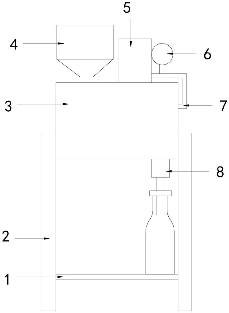
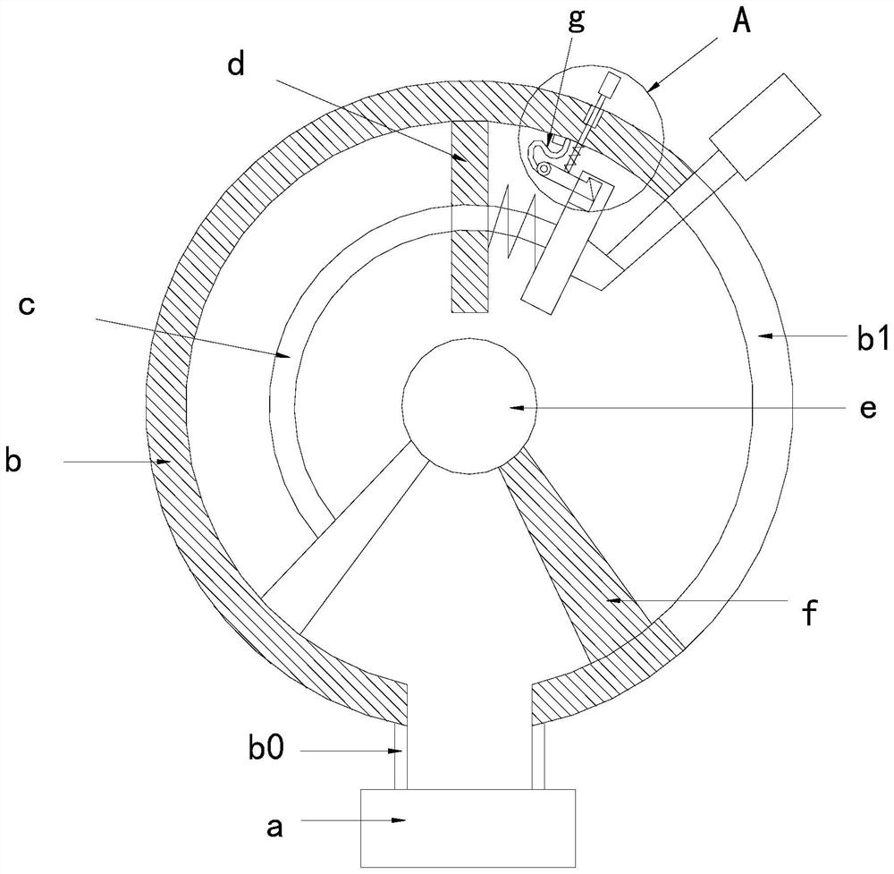
[0026]SeeFigure 1-3 , The present invention provides a technical solution for a vacuum filling machine that is convenient for maintenance: its structure includes a pallet 1, a support 2, a working chamber 3, a barrel 4, a vacuum pump 5, a maintenance structure 6, a rubber tube 7, and a valve 8. The two sides of the cavity 3 are welded with brackets 2 respectively, and the bottom of the working cavity 3 is equipped with a valve 8. The supporting plate 1 is arranged under the valve 8 and connected with the bracket 2, and the top of the working cavity 3 is equipped with a barrel 4 , Vacuum pump 5, said vacuum pump 5 is connected to working chamber 3 through a hose 7, said hose 7 communicates with an overhaul structure 6, said overhaul structure 6 includes an overhaul valve a, a housing b, a movable part c, and a fixed plate d , The fixed shaft e, the sealing plate f, the bottom of the shell b is provided with a through hole b0, the through hole b0 is connected to the hose 7 through the...

Embodiment 2

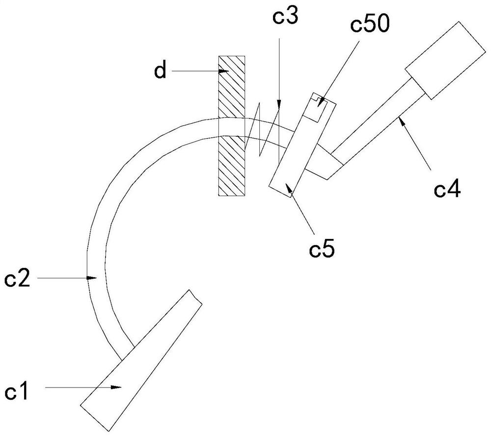
[0029]SeeFigure 1-4, The present invention provides a technical solution for a vacuum filling machine that is convenient for maintenance: its structure includes a pallet 1, a support 2, a working chamber 3, a barrel 4, a vacuum pump 5, a maintenance structure 6, a rubber tube 7, and a valve 8. The two sides of the cavity 3 are welded with brackets 2 respectively, and the bottom of the working cavity 3 is equipped with a valve 8. The supporting plate 1 is arranged under the valve 8 and connected with the bracket 2, and the top of the working cavity 3 is equipped with a barrel 4 , Vacuum pump 5, said vacuum pump 5 is connected to working chamber 3 through a hose 7, said hose 7 communicates with an overhaul structure 6, said overhaul structure 6 includes an overhaul valve a, a housing b, a movable part c, and a fixed plate d , The fixed shaft e, the sealing plate f, the bottom of the shell b is provided with a through hole b0, the through hole b0 is connected to the hose 7 through the ...


PUM


Abstract

The invention discloses a vacuum filling machine convenient to overhaul. The vacuum filling machine structurally comprises a supporting plate, supports, a working cavity, a charging barrel, a vacuum pump, an overhaul structure, a rubber pipe and a valve, wherein the supports are welded to the two sides of the working cavity correspondingly; the valve is mounted at the bottom of the working cavity;the supporting plate is arranged below the valve and connected with the supports; the charging barrel and the vacuum pump are mounted at the top of the working cavity; the vacuum pump is connected with the working cavity through the rubber pipe; the rubber pipe communicates with the overhaul structure; the overhaul structure comprises an overhaul valve, a shell, a movable part, a fixed plate, a fixed shaft and a sealing plate; a through hole is formed in the bottom of the shell and communicates with the rubber pipe through the overhaul valve; the fixed shaft is connected to the inner middle of the shell; and the sealing plate is connected between the fixed shaft and the shell. The vacuum filling machine has the beneficial effects that whether the rubber pipe leaks air or not can be directly checked through the overhaul structure, so that overhaul is more convenient and faster; and troubleshooting of other faults is not hindered during overhaul, and the overhaul efficiency is improved.

Description

Technical field[0001]The invention relates to the field of filling machines, in particular to a vacuum filling machine which is convenient for maintenance.Background technique[0002]The vacuum filling machine is a machine that fills the bottle when the pressure in the bottle is lower than the atmospheric pressure. It uses continuous vacuum suction to pump the product into the container. The continuous suction is connected to a vacuum chamber and a special filling valve. The vacuum pump is produced.[0003]During use, there will be cases where the hose leaks and cannot be filled. At this time, it needs to be checked one by one during maintenance, and additional equipment is required to check the hose for leaks, which is more troublesome.Summary of the invention[0004]The main purpose of the present invention is to overcome the shortcomings of the prior art and provide a vacuum filling machine that is convenient for maintenance.[0005]The present invention adopts the following technical so...

Claims


Application Information

Patent Timeline
Patent Type & Authority Applications(China)
IPC IPC(8): B67C3/16B67C3/22B67C3/24B67C3/26
CPCB67C3/16B67C3/22B67C3/24B67C3/2634
Inventor 胡艳锋
Owner 胡艳锋
Learn More