Square battery charge-discharge test motion mechanism and application method

A technology for charge and discharge testing and prismatic batteries, which is applied to battery pack components, electrical measuring instrument components, circuits, etc., can solve problems such as waste of battery testing equipment resources, and reduce human and material resources.

Pending Publication Date: 2020-12-29
ZHEJIANG HANGKE TECH
View PDF0 Cites 1 Cited by
  • Summary
  • Abstract
  • Description
  • Claims
  • Application Information

AI Technical Summary

Problems solved by technology

Therefore, in the actual production process, there will be a certain waste of resources in battery testing equipment

Method used


Image

  • Square battery charge-discharge test motion mechanism and application method
  • Square battery charge-discharge test motion mechanism and application method
  • Square battery charge-discharge test motion mechanism and application method

Examples


Embodiment 1

[0038] Embodiment 1 A prismatic battery charge and discharge test movement mechanism according to the present invention includes:

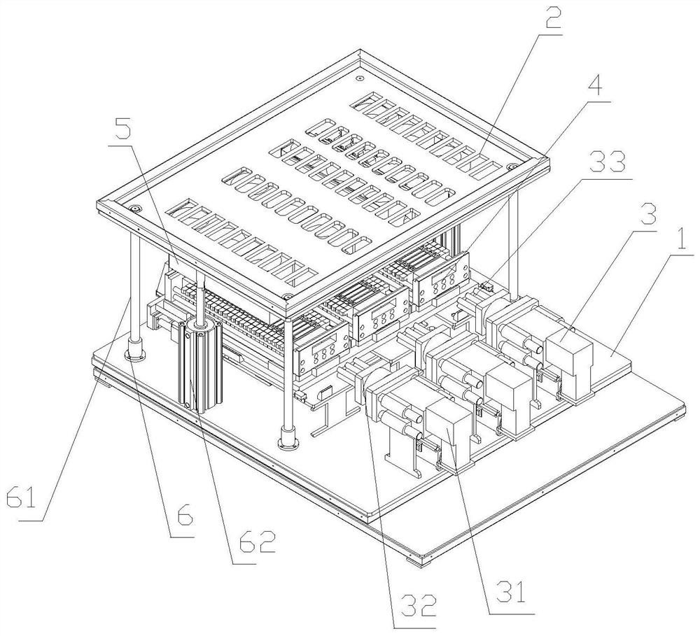
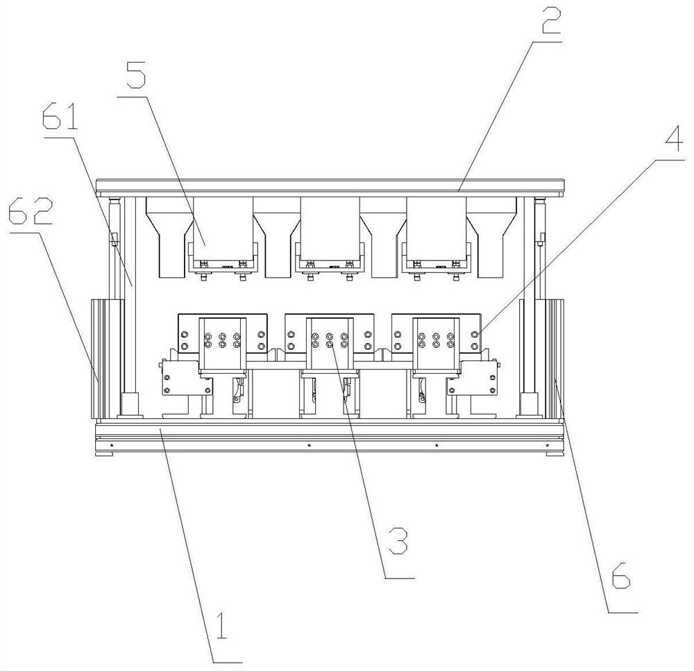
[0039] The bottom plate 1 is installed, and an installation plane is arranged on the surface, which is used to support the voltage regulation drive mechanism and the battery tray mechanism of the square battery charge and discharge test movement mechanism;

[0040] The pressure regulating drive mechanism 3 is arranged on the installation plane, including a drive part and a push part, wherein the drive part is fixed on the installation plane, and the driving end of the drive part is aligned with the battery tray mechanism, and stretches in a direction parallel to the installation plane , used to drive the pushing part to move; the pushing part is installed on the driving end of the driving part, and is used to pressurize or release the battery tray mechanism;

[0041] The battery tray mechanism 4 is arranged on the installation plane, and includes ...

Embodiment 2

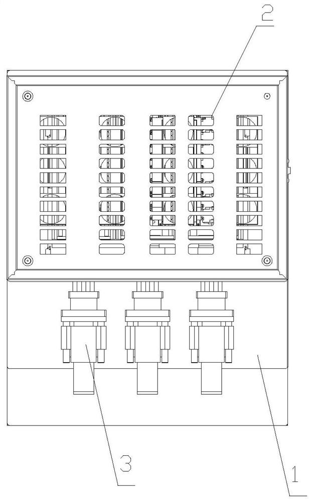
[0050] Embodiment 2 The charging and discharging test movement mechanism of the square battery of the present invention includes a mounting base plate 1 for supporting, a voltage regulating driving mechanism 3 for pressurizing and releasing the battery tray mechanism, and a driving mechanism for carrying the square battery. The battery tray mechanism 4, the positive and negative electrode conduction mechanism for contacting the positive and negative poles of the square battery, wherein the positive and negative electrode conduction mechanism includes a top plate 2 for installing and supporting the probe mechanism, for connecting with the positive and negative poles of the square battery A probe mechanism 5 for contacting the positive and negative poles of the square battery and a jacking mechanism 6 for driving the installation top plate and the probe mechanism to move up and down, wherein:

[0051] The installation bottom plate and the installation top plate can be aluminum pl...

Embodiment 3

[0062] Embodiment 3 An application method of a square battery charging and discharging testing motion mechanism according to the present invention, comprising the following steps:

[0063] 1) Place the battery tray 43 containing seventy-two square batteries on the bottom plate of the battery tray mechanism 4, which is supported by the bottom plate 41 of the battery tray mechanism 4, and is limited by the stopper 42. When the battery After the tray 43 is in place, the pressure regulating drive mechanism 3 starts to act;

[0064] 2) The speed reducer 31 of the voltage regulating drive mechanism 3 performs power action to push the clamping shaft 33 to move. When the tight hole 4321 cooperates, push the front and rear pushing block 433 to move, and then pressurize the square battery;

[0065] 3) After the square battery is pressurized, the distance between the batteries changes, and the position data of each battery is obtained by the CCD camera 53;

[0066] 4) The position data...


PUM


Abstract

The invention provides a square battery charge-discharge test motion mechanism and an application method. The motion mechanism comprises a mounting bottom plate, a voltage regulation driving mechanism, a battery tray mechanism and a positive and negative electrode conduction mechanism, wherein the voltage regulation driving mechanism is arranged on a mounting plane, comprises a driving part and apushing part and is used for pressurizing or releasing a battery tray mechanism; the battery tray mechanism is arranged on the mounting plane, comprises a bottom plate, a stop block and a plurality ofgroups of battery trays and is used for bearing a square battery; and the positive and negative electrode conduction mechanism is arranged on the mounting plane, comprises a top plate, a probe mechanism and a jacking mechanism and is used for being in contact with the positive and negative electrodes of the square battery. The application method comprises the following steps: placing the batterytrays on the bottom plate, and pressurizing the square battery by the voltage regulation driving mechanism after the battery trays are in place; and feeding back position data of each battery to an electric cylinder assembly by a CCD camera so as to adjust the position of a probe, and detecting the square battery. The square battery charge-discharge test motion mechanism and the application methodhave the beneficial effects that the operation is fully automatic, and the battery trays are high in compatibility; and the test probe can also be self-adjusted and self-adapted to different types ofbatteries.

Description

technical field [0001] The invention relates to a movement mechanism for charging and discharging a square battery and an application method thereof, belonging to the field of testing square batteries. Background technique [0002] A square battery is one type of battery. In a square battery, the positive and negative poles are located at both ends of the top surface of the square battery. When the battery model is different, the distance between the positive and negative poles will change accordingly. Therefore, in the charge and discharge test, when the battery model is changed, the test probes need to be replaced accordingly. In the previous charging and discharging test, the test probes were fixed, and designated charging and discharging equipment was required to match the corresponding type of battery. Therefore, in the actual production process, there will be a certain waste of resources in the battery testing equipment. Contents of the invention [0003] In order ...

Claims


Application Information

Patent Timeline
Patent Type & Authority Applications(China)
IPC IPC(8): G01R31/385G01R1/04G01R1/067H01M2/10
CPCG01R31/385G01R1/0408G01R1/06705G01R1/06794Y02E60/10
Inventor 曹骥曹政蔡清源虞明亮
Owner ZHEJIANG HANGKE TECH
Why Eureka
Try Eureka