Eureka AIR delivers breakthrough ideas for toughest innovation challenges, trusted by R&D personnel around the world.

Transposition structure for surface-mounted component

A technology of transposing structure and components, which is applied in the direction of assembling printed circuits, electrical components, and electrical components with electrical components, which can solve the problem of lack of spare disassembly and assembly structures, difficulty in screwing bolts, and difficulty in separating the transposition board from the servo motor, etc. question

Active Publication Date: 2020-12-29
江苏贺鸿智能科技有限公司
View PDF7 Cites 0 Cited by
  • Summary
  • Abstract
  • Description
  • Claims
  • Application Information

AI Technical Summary

Problems solved by technology

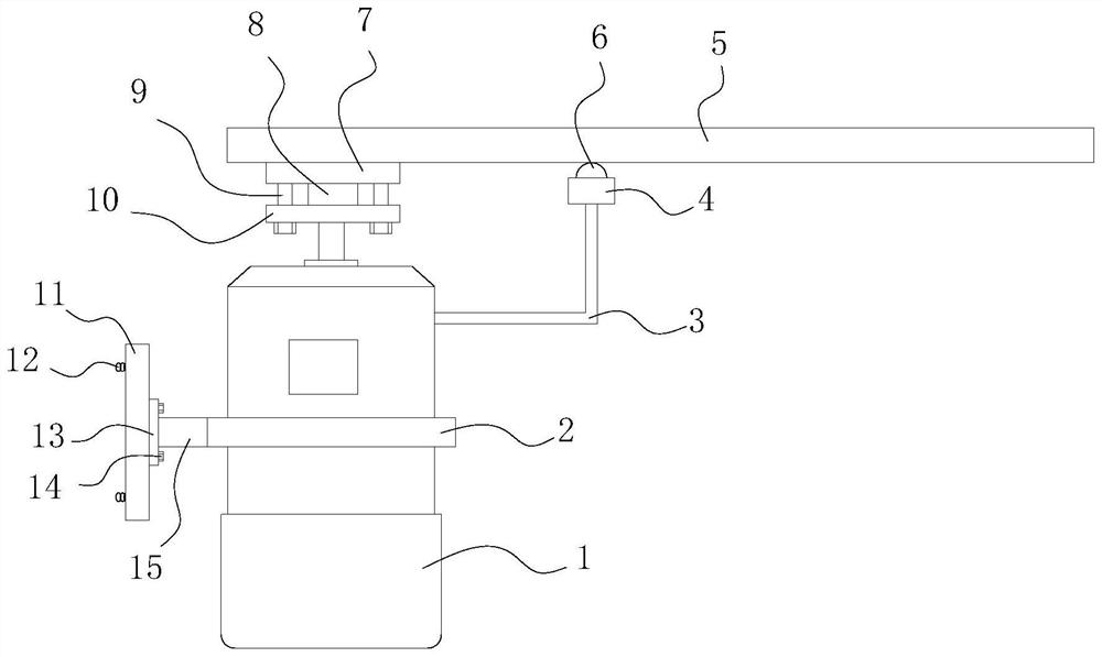
[0004] In view of the deficiencies in the prior art, the purpose of the present invention is to provide a transposition structure for surface-mounted components to solve the problem of the bolts connecting the transposition board and the output end of the servo motor proposed in the above-mentioned background technology after installation. The screw part is in a hidden state, and when the bolts are difficult to twist due to corrosion and other reasons in the later stage, due to the lack of a spare disassembly structure, it is difficult to separate the transpose plate from the servo motor. The invention realizes the bare connection between the transpose plate and the servo motor Part of the screw part of the bolt is convenient for dismantling the transposition plate by sawing off the exposed part of the bolt in the later stage

Method used


Image

  • Transposition structure for surface-mounted component
  • Transposition structure for surface-mounted component
  • Transposition structure for surface-mounted component

Examples


Embodiment Construction

[0019] In order to make the technical means, creative features, goals and effects achieved by the present invention easy to understand, the present invention will be further described below in conjunction with specific embodiments.

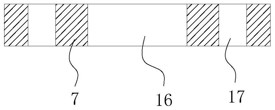
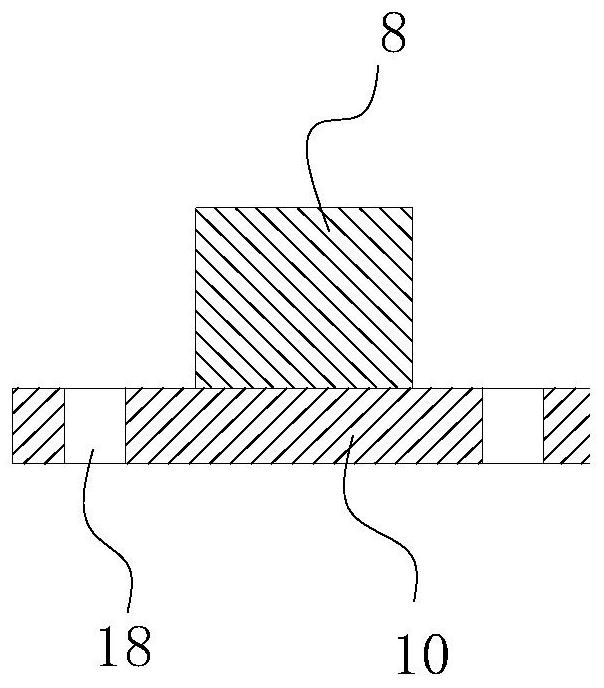
[0020] see Figure 1-Figure 5 , the present invention provides a technical solution: a transposition structure for surface mount components, including a servo motor 1 and a transpose plate 6 for transferring label components, the output end of the servo motor 1 is fixedly connected with a connection plate 10. One side of the lower surface of the transposition plate 6 is fixedly connected with the boss 7 that matches the connection plate 10, and the boss 7 is fixed at the position where the transposition plate 6 is connected to the connection plate 10, so as to realize partial thickening of the transposition plate 6 The connection part is beneficial to reduce the production materials of the transpose plate 6 .

[0021] The middle part of the lower...


PUM


Abstract

The invention provides a transposition structure for a surface-mounted component. The transposition structure comprises a servo motor and a transposition plate for transferring a labeled component, wherein the output end of the servo motor is fixedly connected with a connecting disc, one side of the lower surface of the transposition plate is fixedly connected with a boss matched with the connecting disc, a square opening is formed in the middle of the lower surface of the boss, a square column matched with the square opening is fixedly connected to the face, facing the boss, of the connectingdisc, a plurality of threaded through holes are annularly formed in the face, facing the connecting disc, of the boss at equal intervals, a plurality of round holes matched with the threaded throughholes are formed in the connecting disc, and first connecting bolts in threaded connection with the threaded through holes are arranged in the round holes. Compared with the prior art, the transposition structure of the invention has the following beneficial effects that part of screw rod parts of bolts for connecting the transposition plate and the servo motor are exposed, so that the transposition plate can be conveniently disassembled in the mode of sawing off the exposed parts of the bolts in the later period.

Description

technical field [0001] The invention relates to a transposition structure for surface-mounted components, which belongs to the field of component production equipment. Background technique [0002] Surface mount technology, referred to as SMT, has penetrated into various fields as a new generation of electronic assembly technology. SMT products have the advantages of compact structure, small size, vibration resistance, impact resistance, good high-frequency characteristics, and high production efficiency. SMT has occupied a leading position in the circuit board assembly process. [0003] In the production process of surface mount components, servo motors are often used to drive the transposition board used to transfer surface mount components between adjacent processes. The transposition board is often fixedly connected to the output end of the servo motor by bolts, but the connection After the transpose plate and the bolts at the output end of the servo motor are installed...

Claims


Application Information

Patent Timeline
IPC IPC(8): H05K13/04H05K3/30
CPCH05K3/303H05K13/0434H05K13/046H05K13/0495
Inventor 朱利明
Owner 江苏贺鸿智能科技有限公司
Why Eureka
Eureka Blog
Learn More