A rubber sealing ring cutting machine

A technology of rubber sealing ring and cutting machine, applied in metal processing and other directions, can solve the problem of rubber ring easily sticking to the cutting device, etc., and achieve the effect of easy collection, uniform and efficient cutting

Active Publication Date: 2022-04-12
湖南科盛智能装备制造有限公司
View PDF0 Cites 0 Cited by
  • Summary
  • Abstract
  • Description
  • Claims
  • Application Information

AI Technical Summary

Problems solved by technology

[0005] In order to overcome the disadvantages of the prior art that the rubber ring is easy to stick to the cutting device when cutting the rubber ring, people need to manually remove the rubber ring. Ring Better Drop Rubber Seal Ring Cutting Machine

Method used


Image

  • A rubber sealing ring cutting machine
  • A rubber sealing ring cutting machine
  • A rubber sealing ring cutting machine

Examples


Embodiment 1

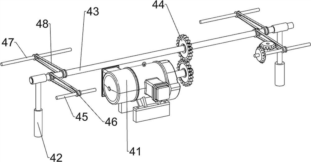
[0026] A rubber sealing ring cutting machine, such as Figure 1-5 As shown, it includes a bottom plate 1, a frame 2, a slideway 3, a transmission device 4, a clamping and feeding device 5 and a cutting device 6. The top of the bottom plate 1 is symmetrically provided with a frame 2, and the middle of the top of the bottom plate 1 is provided with a slideway 3. , The slideway 3 is located between the frame 2, the top of the bottom plate 1 is provided with a transmission device 4, the frame 2 is provided with a clamping and feeding device 5, and the frame 2 is provided with a cutting device 6.

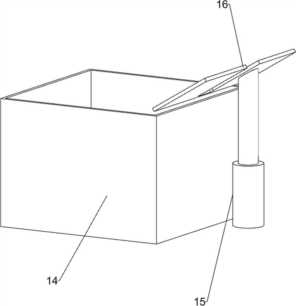
[0027] When people need to use this machine, first people put the rubber ring on the slideway 3, then place the collection tool on the bottom plate 1 on the left side of the slideway 3, and then start the transmission device 4, so that the transmission device 4 drives the clip The tight feeding device 5 and the cutting device 6 operate, and the operation of the clamping feeding device 5 ...

Embodiment 2

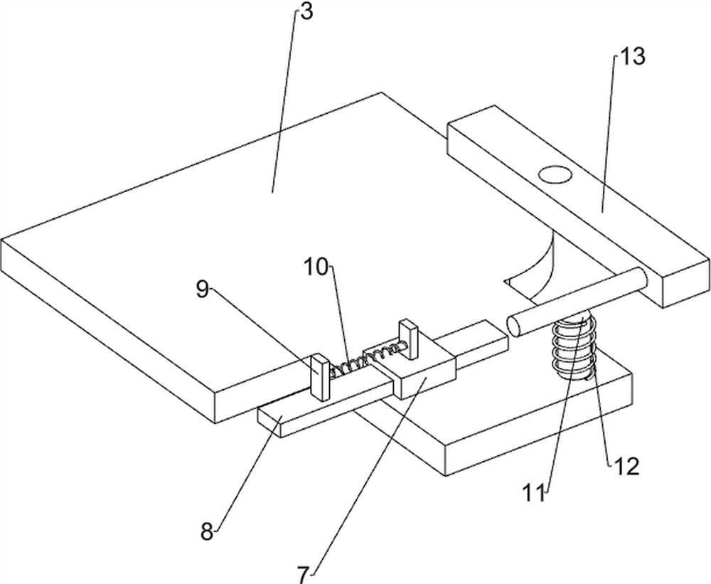
[0035] On the basis of Example 1, such as Figure 6-7 As shown, it also includes a guide block 7, a push plate 8, a fixed block 9, a second elastic member 10, a second connecting rod 11, a third elastic member 12 and a rotating block 13, and a guide block is provided on the left front side of the top of the slideway 3. 7. A push plate 8 is slidingly provided in the guide block 7, and a fixed block 9 is provided on the push plate 8 and the guide block 7, and a second elastic member 10 is arranged between the two fixed blocks 9, and the second elastic member 10 is a tension spring, the left front side of the top of the slideway 3 is provided with a second connecting rod 11, the second connecting rod 11 is covered with a third elastic member 12, and the third elastic member 12 is a torsion spring, and the second connecting rod 11 The upper rotation type is provided with a rotating block 13, the third elastic member 12 is connected with the rotating block 13 and the slideway 3, th...


PUM


Abstract

The invention relates to a cutting machine, in particular to a rubber sealing ring cutting machine. Provided is a rubber sealing ring cutting machine capable of uniformly cutting the rubber ring and enabling the rubber ring to drop better. A rubber sealing ring cutting machine, comprising: a bottom plate, a frame is symmetrically arranged on the top of the bottom plate; a slideway, a slideway is arranged in the middle of the top of the bottom plate; There is a clamping feeding device; a cutting device, and a cutting device is installed on the frame. The present invention realizes the intermittent transmission of the rubber ring to the left by clamping the feeding device, and then under the cooperation of the transmission device and the cutting device, the rubber ring can be cut evenly and efficiently; The ring falls into the collection box when it falls downwards, so that it is convenient to collect the rubber ring, and the baffle plate can block the rubber ring so that it is not easy to fall out of the collection box.

Description

technical field [0001] The invention relates to a cutting machine, in particular to a rubber sealing ring cutting machine. Background technique [0002] The rubber sealing ring is an annular cover composed of one or several parts, which is fixed on a ring or washer of the bearing and contacts with another ring or washer or forms a narrow labyrinth gap to prevent the leakage of lubricating oil and the intrusion of foreign objects. [0003] The rubber sealing ring is a round rubber product, which is generally used for leak prevention. Natural rubber has high elasticity at room temperature, slightly plastic, has very good mechanical strength, low hysteresis loss, and low heat generation during multiple deformations. Therefore, its flex resistance is also very good, and because it is a non-polar rubber, it has good electrical insulation performance. Before the rubber is made into a rubber sealing ring, it usually needs to be cut. The current traditional method is manual measurem...

Claims


Application Information

Patent Timeline
Patent Type & Authority Patents(China)
IPC IPC(8): B26D1/10B26D5/16B26D7/06B26D7/02B26D7/32
CPCB26D1/10B26D5/16B26D7/06B26D7/02B26D7/32
Inventor 周智荣
Owner 湖南科盛智能装备制造有限公司
Why Eureka
Try Eureka