
Current bias circuit with adjustable and compensable current value

A current bias and compensation circuit technology, applied in the direction of adjusting electrical variables, control/regulating systems, instruments, etc., can solve problems such as differences in resistance change characteristics and inability to truly achieve temperature compensation.

Active Publication Date: 2021-01-01
JIANGSU HAIDONG SEMICON TECH CO LTD
View PDF25 Cites 2 Cited by
  • Summary
  • Abstract
  • Description
  • Claims
  • Application Information

AI Technical Summary

Problems solved by technology

At present, the so-called zero temperature coefficient current bias circuit uses two different types of resistors, such as well resistors and high-resistance polycrystalline resistors, to compensate by using their opposite temperature coefficient characteristics, and the temperature of these two types of resistors The characteristics are not exactly the same, that is, as the temperature changes, the resistance change characteristics of the two types of resistors are different, so temperature compensation cannot be truly achieved

Method used


Image

  • Current bias circuit with adjustable and compensable current value
  • Current bias circuit with adjustable and compensable current value
  • Current bias circuit with adjustable and compensable current value

Examples


Embodiment Construction

[0029] The technical solutions of the present invention will be clearly and completely described below in conjunction with the accompanying drawings. Apparently, the described embodiments are some of the embodiments of the present invention, but not all of them. Based on the embodiments of the present invention, all other embodiments obtained by persons of ordinary skill in the art without making creative efforts belong to the protection scope of the present invention.

[0030] In the description of the present invention, it should be noted that the terms "center", "upper", "lower", "left", "right", "vertical", "horizontal", "inner", "outer" etc. The indicated orientation or positional relationship is based on the orientation or positional relationship shown in the drawings, and is only for the convenience of describing the present invention and simplifying the description, rather than indicating or implying that the referred device or element must have a specific orientation, ...


PUM


Abstract

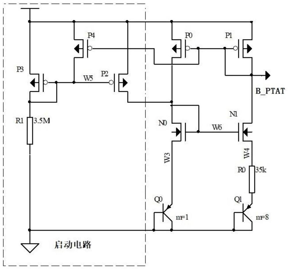
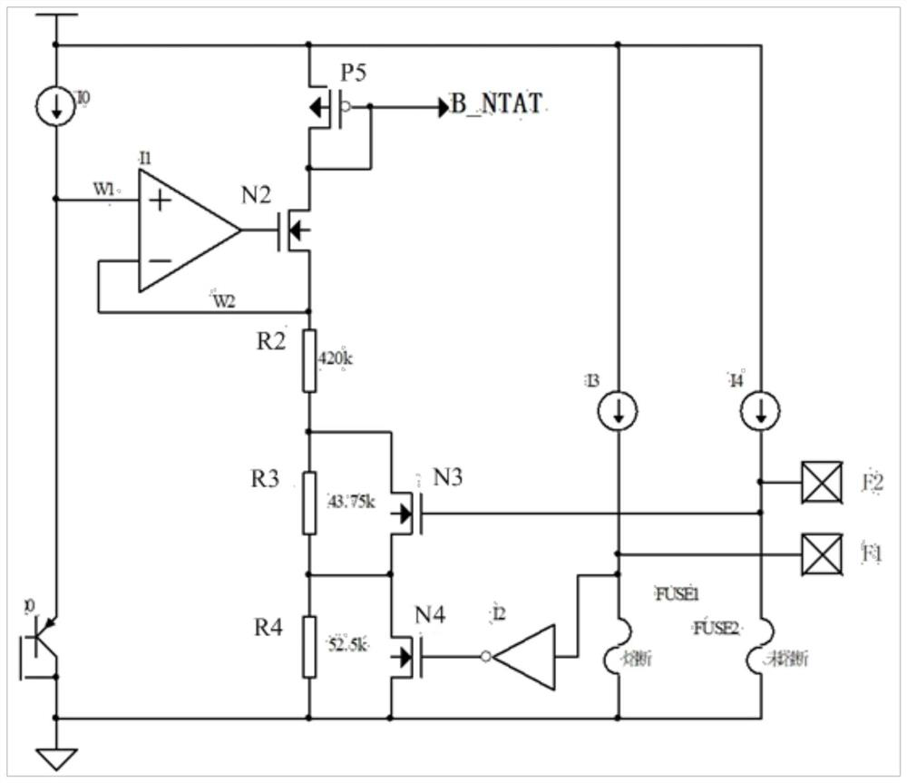
The invention relates to the technical field of integrated circuits, in particular to a current bias circuit with an adjustable and compensable current value. The circuit comprises a starting circuit,a positive temperature coefficient current bias circuit, a negative temperature coefficient current bias circuit and a positive and negative temperature coefficient current bias selection compensation circuit. The starting circuit is used for triggering and starting the positive temperature coefficient current biasing circuit; the positive temperature coefficient current bias circuit and the negative temperature coefficient current bias circuit output a current to the positive and negative temperature coefficient current bias selection compensation circuit, and the positive and negative temperature coefficient current bias selection compensation circuit performs selection compensation according to the received current value. According to the present invention, the problem that positive and negative temperature coefficients cannot be truly compensated in the prior art is solved. The circuit comprises the positive temperature coefficient current bias circuit and the negative temperaturecoefficient current bias circuit at the same time, so that the problems that in the prior art, only the positive temperature coefficient current bias circuit or the negative temperature coefficient current bias circuit is included, and the circuit is more single, are solved.

Description

technical field [0001] The invention relates to the technical field of integrated circuits, in particular to a current bias circuit with adjustable and compensable current value. Background technique [0002] In integrated circuit design, if the amplifier composed of semiconductor devices such as transistors and MOS tubes can amplify the signal voltage without distortion, it must ensure that these devices are in a specific working state, that is, their operating points should be set, and these The setting of the operating point can be realized through an external circuit, and this external circuit is called a bias circuit. Of course, in addition to amplifiers, many circuit structures in integrated circuits must be provided with operating points or stable initial states by bias circuits. These circuit structures are usually called follow-up circuits driven by bias circuits. Therefore, bias circuits in integrated circuits It is very important and widely used. According to th...

Claims


Application Information

Patent Timeline
Patent Type & Authority Applications(China)
IPC IPC(8): G05F1/567
CPCG05F1/567
Inventor 居水容黄传伟
Owner JIANGSU HAIDONG SEMICON TECH CO LTD
Learn More