A rain-shielding powder remover
A powder removal and powder board technology, which is applied in beehives, applications, beekeeping, etc., can solve the problems of unfavorable use of powder removers in rainy days, loss of beekeepers and bee colonies, etc., to reduce the chance of wetting and increase the speed of powder removal Fast, improve the effect of powder removal efficiency
- Summary
- Abstract
- Description
- Claims
- Application Information
AI Technical Summary
Problems solved by technology
Method used
Image
Examples
Embodiment 1
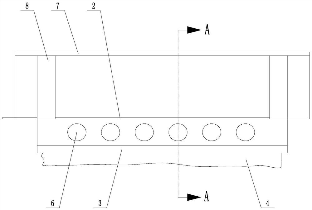
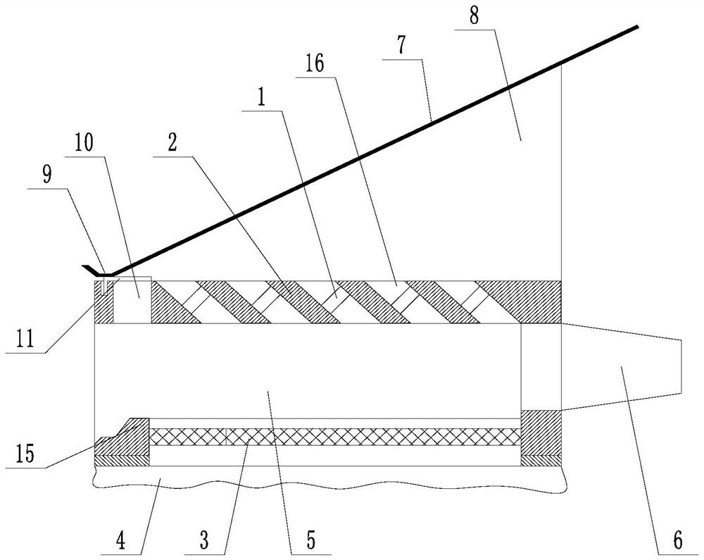
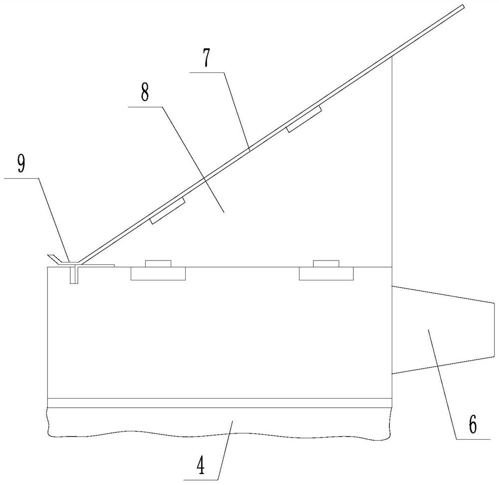
[0043] Such as Figure 1 to Figure 5 The rain-proof powder remover shown includes a powder remover plate 2 with a powder remover ring 1, a powder leakage grid 3 located under the powder removal plate 2, and a powder receiving bag located under the powder leakage grid 3 4. The powder removing plate 2 and the powder leaking grid 3 form a transitional space 5 for honeybees to enter and exit the beehive. Several one-way passages 6 are arranged on the front side of the transitional space 5, and the rear side of the transitional space 5 is open; Including a rain shield 7 positioned above the powder removal plate 2.
[0044] Preferably, both sides of the top of the powder removing plate 2 are detachably connected to support blocks 8, the top surface of the support block 8 is a slope, and the slope is inclined upward from the inside to the outside, and the rain shield 7 is detachably connected to the On the slopes on both sides, and the bottom of the rain shield 7 is in contact with ...
Embodiment 2
[0051] Such as Figure 1 to Figure 9 In the shown rain-shielding powder remover, on the basis of Embodiment 1, several powder discharge holes 10 are opened on the powder remover plate 2, and opening and closing parts for blocking and opening the powder discharge holes 10 are also included. . Some powder holes 10 are distributed along a straight line on the powder removal plate 2, and the opening and closing parts are cover plates 11, and some gaps 12 are provided at equal distances on the cover plate 11, and the gaps 12 are aligned with the powder holes 10. One matching, and the cover plate 11 can move linearly along the connection direction of several powder discharge holes 10;
[0052] When the cover plate 11 is moved to the powder discharging station, the gap 12 is directly opposite to the powder discharging hole 10, and the powder discharging hole 10 is opened;
[0053] When the cover plate 11 moves to the closing position, the notch 12 is misaligned with the correspondi...
Embodiment 3
[0058] On the basis of any of the above-mentioned embodiments, the powder receiving bag in this embodiment Figure 10 As shown, it includes a frame 401 and a waterproof pouch 402 fixed at the bottom of the frame 401 , and the frame 401 is detachably connected to the powder leakage grill 3 .
[0059] This embodiment uses a waterproof pouch as its main part, and the top frame is used to install the waterproof pouch, and at the same time connect it magnetically to the upper powder remover. The advantage is that first, it only needs to ensure the sealing between the waterproof pouch and the frame It can ensure stable waterproof and avoid the pollen received from being wet and wasted; secondly, the pouch material has good folding and storage performance, which is convenient for reducing the volume and space occupation in the process of moving to the field; and in this scheme, the frame and The magnetic suction connection between the powder leakage grilles can be flexibly replaced a...
PUM
 Abstract
Description
Claims
Application Information
 - R&D
- Intellectual Property
- Life Sciences
- Materials
- Tech Scout
- Unparalleled Data Quality
- Higher Quality Content
- 60% Fewer Hallucinations
Browse by: Latest US Patents, China's latest patents, Technical Efficacy Thesaurus, Application Domain, Technology Topic, Popular Technical Reports.
© 2025 PatSnap. All rights reserved.Legal|Privacy policy|Modern Slavery Act Transparency Statement|Sitemap|About US| Contact US: help@patsnap.com


