Multifunctional microfluidic detection chip

A detection chip and microfluidic technology, applied in laboratory containers, transportation and packaging, dissolution, etc., can solve the problem of small volume of diluent quantitative cavity and sample quantitative cavity, large sample usage, large blood sample volume, etc. problems, to improve the effectiveness of judgment and detection, simplify the chip structure, and improve the accuracy

Active Publication Date: 2021-01-05
NANJING LANSION BIOTECH CO LTD
View PDF4 Cites 12 Cited by
  • Summary
  • Abstract
  • Description
  • Claims
  • Application Information

AI Technical Summary

Problems solved by technology

[0003] However, the microfluidic detection chip technology in the prior art still has some defects in practical application, such as complex structure, large sample usage, inaccurate detection results, too small volume ratio of diluent quantification chamber and sample quantification chamber, production high cost
At present, the centrifugal microfluidic detection chip on the market requires a large amount of blood sample, which is not suitable for clinical blood collection detection of infants, especially newborns, and critically ill patients, and lacks effective quality control functions; so it is necessary to develop a centrifugal microfluidic chip. The detection chip has a simple structure, a small amount of samples can be injected at a time, and multiple indicators can be detected in a small volume. The production cost is low, suitable for mass production, and the detection results are more accurate. At the same time, multiple samples can be detected after chip assembly

Method used


Image

  • Multifunctional microfluidic detection chip
  • Multifunctional microfluidic detection chip
  • Multifunctional microfluidic detection chip

Examples


Embodiment Construction

[0040] The technical solution of the present invention will be described in detail below in conjunction with the accompanying drawings. It should be understood that the specific embodiments described here are only used to explain the present invention, and are not intended to limit the present invention. The scope of the present application is not limited by these embodiments, but the scope of the patent application shall prevail. In order to provide a clearer description and enable those familiar with the art to understand the application content of this application, the various parts in the diagram are not necessarily drawn according to their relative sizes, and the ratio of certain sizes to other relevant dimensions will be highlighted The exaggerated, irrelevant or unimportant details are not fully drawn in order to simplify the diagram.

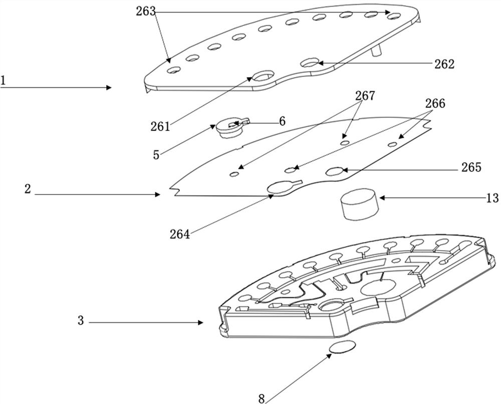
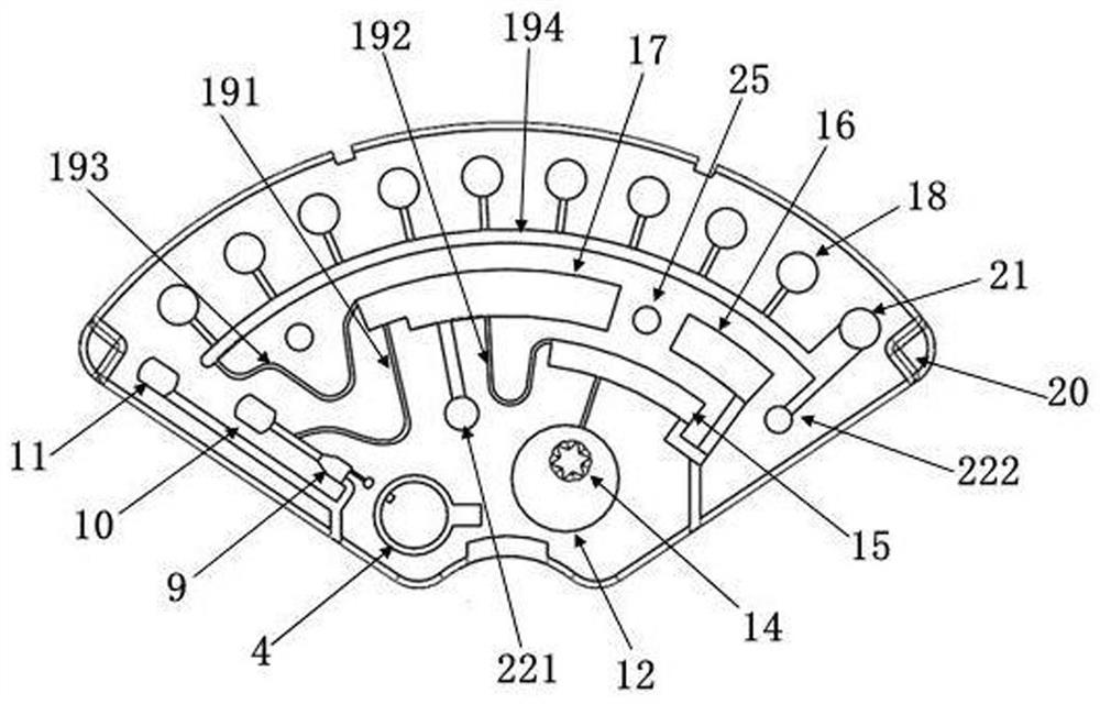
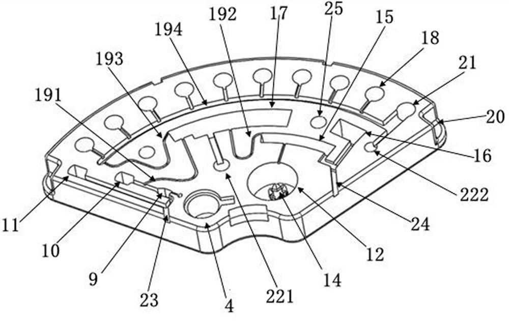
[0041] Such as Figure 1-4 As shown, the multifunctional microfluidic detection chip of the present invention is made by mold injecti...


PUM

PropertyMeasurementUnit
radiusaaaaaaaaaa

Abstract

The invention discloses a multifunctional micro-fluidic detection chip. The detection chip comprises a chip body, wherein a sample injection cavity, a sample quantifying cavity, a sample overflow cavity, a diluent storage cavity, a diluent quantifying cavity, a diluent overflow cavity, a quantitative uniform mixing cavity, a reaction cavity and an air hole are formed in the chip body; a to-be-detected sample is injected into the sample injection cavity and enters the sample quantifying cavity through a micro-channel, and redundant samples enter the sample overflow cavity; diluent in the diluent storage cavity enters the diluent quantifying cavity through the micro-channel, and redundant diluent enters the diluent overflow cavity; the reaction cavity comprises one or more reaction chambersand a sample blank chamber; and after the sample in the sample quantifying cavity and the diluent in the diluent quantifying cavity are uniformly mixed in the quantitative uniform mixing cavity, the obtained mixture enters the reaction chamber through the micro-channel for a reaction with a reaction reagent to be detected, and meanwhile, the mixture enters the sample blank chamber to be used as asample blank for detection. The multifunctional micro-fluidic detection chip can effectively reduce sample consumption, improve the accuracy of detection results, and detect multiple indexes at the same time.

Description

technical field [0001] The invention belongs to the field of in vitro microfluidic detection, in particular to a multifunctional microfluidic detection chip. Background technique [0002] Microfluidic detection chip technology integrates the basic operation units of sample preparation, reaction, separation, and detection in the process of biological, chemical, and medical analysis into a micron-scale chip, and automatically completes the entire analysis process. It has great potential in the fields of biology, chemistry and medicine. [0003] However, the microfluidic detection chip technology in the prior art still has some defects in practical application, such as complex structure, large sample usage, inaccurate detection results, too small volume ratio of diluent quantification chamber and sample quantification chamber, production High cost etc. At present, the centrifugal microfluidic detection chip on the market requires a large amount of blood sample, which is not s...

Claims


Application Information

Patent Timeline
Patent Type & Authority Applications(China)
IPC IPC(8): B01L3/00B01F13/00B01F15/04B01F3/08
CPCB01L3/5027B01F23/45B01F33/3017B01F35/83B01F2101/23B01L2200/10B01L2200/0684B01L2200/16B01L2400/0409B01L2300/087B01L2300/0864B01L2300/0816B01L2200/027B01L2200/028B01L2200/0647B01L2300/0832B01L2300/0861B01F23/483B01F23/451B01L3/502723
Inventor 许行尚杰弗瑞·陈
Owner NANJING LANSION BIOTECH CO LTD
Why Eureka
Try Eureka