Logistics clamping holding machine

A clamping machine and logistics technology, applied in the field of logistics, can solve the problems of reducing the protection effect of the carton on the inner items, damage to the smooth surface of the carton, etc., and achieve the effect of preventing offset and ensuring integrity.

Inactive Publication Date: 2021-01-05
刘兆喜
View PDF12 Cites 0 Cited by
  • Summary
  • Abstract
  • Description
  • Claims
  • Application Information

AI Technical Summary

Problems solved by technology

[0005] Aiming at the deficiencies of the existing technology, the purpose of the present invention is to provide a logistics clamping machine to solve the problem in the prior art that logistics items are usually packaged in cartons, and items placed obliquely on the inside of the carton are horizontally clamped. ...

Method used


Image

  • Logistics clamping holding machine
  • Logistics clamping holding machine
  • Logistics clamping holding machine

Examples


Embodiment 1

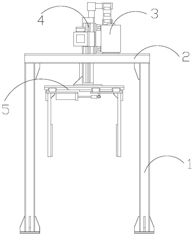
[0028] Example 1: Please refer to Figure 1-Figure 5 , the specific embodiments of the present invention are as follows:

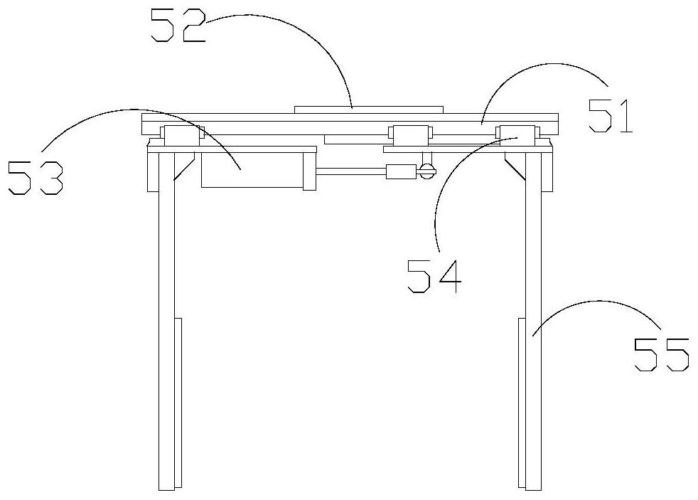
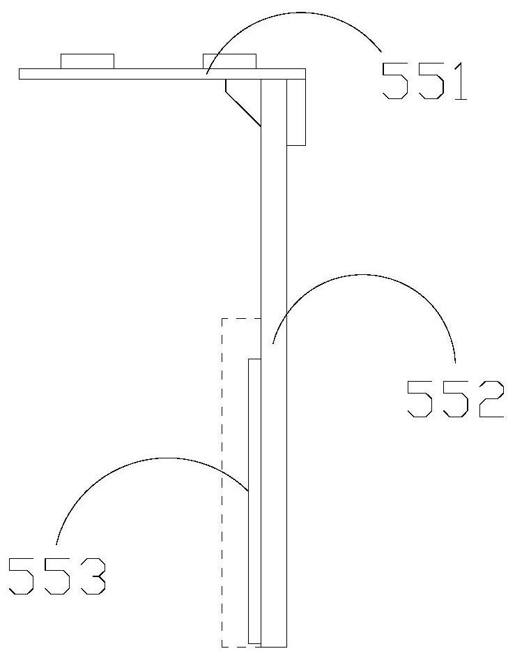
[0029] Its structure includes a frame 1, a transverse guide rail 2, a drive box 3, a longitudinal guide rail 4, and a clamping structure 5. The transverse guide rail 2 is horizontally installed on the upper end of the frame 1 and welded together, and the drive box 3 is installed on the transverse guide rail 2. between them and adopt flexible connection, the longitudinal guide rail 4 is vertically embedded and installed inside the drive box 3 and is located between the transverse guide rails 2, and the clamping structure 5 is vertically installed at the lower end of the longitudinal guide rail 4 and adopts mechanical connection; The clamping structure 5 includes a sliding rail 51, a support frame 52, a cylinder 53, a sliding block 54, and a clamping plate 55. The sliding rail 51 is horizontally installed on the lower end of the supporting frame 52 and welde...

Embodiment 2

[0036] Example 2: Please refer to Figure 5-Figure 8 , the specific embodiments of the present invention are as follows:

[0037] The side splint 53d includes a plate body d1, an exhaust structure d2, and a suction cup structure d3. The exhaust structure d2 is embedded and installed inside the plate body d1 and adopts a flexible connection. The suction cup structure d3 is installed on the left side of the exhaust structure d2 And the inner side is connected, the board body d1 is embedded and installed in the inner side of the embedded frame 53a and adopts a flexible connection.

[0038] refer to Figure 6 , the exhaust structure d2 includes an outer ring d21, a blocking plate d22, a movable shaft d23, and a movable structure d24, the blocking plate d22 is installed inside the outer ring d21 and distributed in a ring, and the movable shaft d23 is movably connected to the outer ring d21 The inner side is mechanically connected with the blocking plate d22 respectively. The mova...


PUM


Abstract

The invention discloses a logistics clamping holding machine. The machine structurally comprises a machine frame, a transverse guide rail, a driving box, a longitudinal guide rail and a clamping holding structure, wherein the transverse guide rail is horizontally installed at the upper end of the machine frame, the driving box is installed between the transverse guide rail, the longitudinal guiderail is vertically embedded into the inner sides of the driving box, and the clamping holding structure is vertically installed at the lower end of the longitudinal guide rail; and the clamping holding structure comprises a sliding rail, a supporting frame, an air cylinder, a sliding block and clamping holding plates, wherein the sliding rail is horizontally installed at the lower end of the supporting frame, the sliding block sleeves the outer side of the sliding rail, the air cylinder is installed between the clamping holding plates, and the clamping holding plates are vertically and fixedlyarranged at the lower end of the sliding block. According to the logistics clamping holding machine, the clamping holding plates are arranged at the lower end of the sliding block, so that right-angle limitation is better formed for the outer side of a carton, the situation that the carton is deviated due to uneven stress is prevented, and the integrity of the outer side smooth surface of the carton is guaranteed; and meanwhile, a suction cup structure is arranged on the inner side of an exhaust structure so that the outer side of the carton can be sucked, and the carton can be further clamped and held more tightly, thereby preventing deviation.

Description

technical field [0001] The invention belongs to the field of logistics, and in particular relates to a logistics clamping machine. Background technique [0002] In logistics transportation, it is usually necessary to sort and transfer the logistics items multiple times to load and unload the logistics items, and these logistics items are usually inside the container. In order to unload or load these logistics items, it is necessary to use the logistics Clamping machine to better load and unload these logistics parts, but the existing technology has the following deficiencies: [0003] Since logistics items are usually packaged in cartons, and for items placed obliquely inside the carton, when they are clamped horizontally, the direction of gravity on the inside will be different, which will cause the carton to shift along with the items inside, and then with the clamping equipment Frictional rotation causes damage to the glossy surface on the outside of the carton, reducing...

Claims


Application Information

Patent Timeline
IPC IPC(8): B65G47/90
CPCB65G47/902
Inventor 刘兆喜
Owner 刘兆喜
Why Eureka
Try Eureka