Winding device for plastic pad packaging

A technology of winding device and plastic mat, which is applied in the direction of transportation and packaging, winding strips, and thin material processing, etc., and can solve the problems of unable to transport plastic mats, cutting plastic mats, and low efficiency of plastic mat winding work

Pending Publication Date: 2021-01-05
冀亚鹏
View PDF8 Cites 2 Cited by
  • Summary
  • Abstract
  • Description
  • Claims
  • Application Information

AI Technical Summary

Problems solved by technology

[0005] In order to overcome that although the existing winding device can realize the rolling work of the plastic mat, it cannot compress the plastic mat, and at the same time, it cannot automatically cut the plastic mat, and it cannot transport the plastic mat. Therefore, the plastic mat cannot be rolled. Due to the disadvantage of low working efficiency, the technical problem of the present invention is to provide a method that can realize the rolling work of the plastic pad, can compress the plastic pad, and can automatically cut the plastic pad at the same time, and can also transport the plastic pad. Work, a winding device for plastic mat packaging that further improves the efficiency of plastic mat winding

Method used


Image

  • Winding device for plastic pad packaging
  • Winding device for plastic pad packaging
  • Winding device for plastic pad packaging

Examples


Embodiment 1

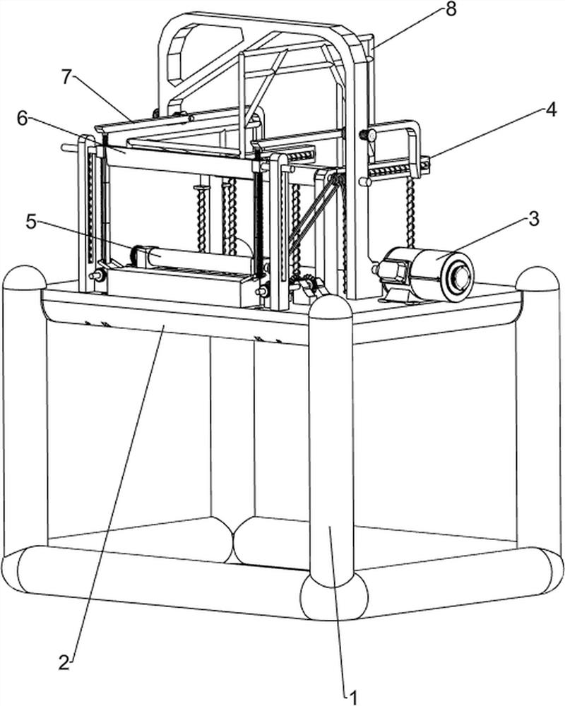
[0068] A winding device for plastic cushion packaging, such as figure 1 As shown, it includes a bottom frame 1, a molding plate 2, a winding mechanism 3 and a pressing mechanism 4. The top of the bottom frame 1 is provided with a molding plate 2, and the top of the molding plate 2 is equipped with a winding mechanism 3, and the molding plate A pressing mechanism 4 is slidably provided between the rear side of the 2 and the rear side of the winding mechanism 3 .

[0069] When a worker needs to rewind the plastic pad, the worker needs to wind one end of the plastic pad around the winding mechanism 3, and then the worker needs to start the winding mechanism 3 to rotate, and the rotation of the winding mechanism 3 can rewind the plastic pad Work, when the rewinding mechanism 3 rolls up the plastic pad to a certain thickness, the hold-down mechanism 4 is compressed, and when the hold-down mechanism 4 resets, the hold-down mechanism 4 will compress the plastic pad on the rewind mech...

Embodiment 2

[0071] In a preferred embodiment of the present invention, as figure 2 As shown, the winding mechanism 3 includes a motor 31, a first transmission shaft 32, a fixed column 33, a reel 34 and a first pulley assembly 35, the right side of the top of the profile plate 2 is fixed with a motor 31 by bolts, and the output of the motor 31 The shaft is provided with a first transmission shaft 32, and a fixed post 33 is installed on the right side of the top of the profile plate 2, and a spool 34 is rotatably connected between the top of the fixed post 33 and the top left side of the profile plate 2, and the right end of the spool 34 is connected to the first A first pulley assembly 35 is connected between the transmission shafts 32 .

[0072] The worker first needs to wrap the end of the plastic pad around the fixed column 33, and then the worker starts the motor 31 to rotate, and the rotation of the motor 31 through the output shaft will drive the first transmission shaft 32 to rotat...

Embodiment 3

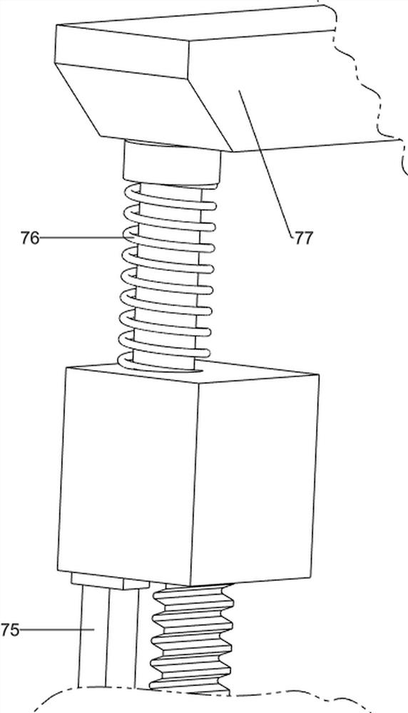
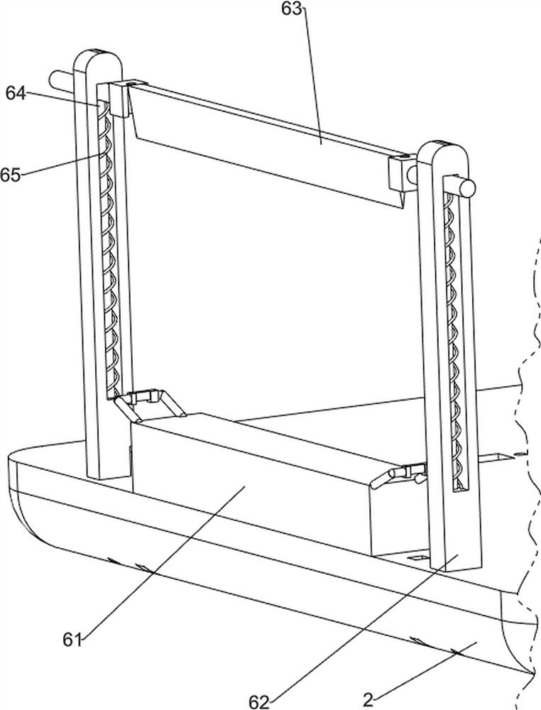
[0074] In a preferred embodiment of the present invention, as figure 1 , image 3 , Figure 4 , Figure 5 , Image 6 , Figure 7 , Figure 8 with Figure 9 As shown, the pressing mechanism 4 includes a first limit frame 41, a fastening column 42, a first extension rod 43 and a first telescopic spring 44, and the rear side of the fixed column 33 and the rear side of the left part of the positioning plate 2 are all provided with There is a first limit frame 41, the first limit frame 41 slides on the fixed column 33, and a fastening column 42 is slid between the two first limit frames 41, and the first limit frame 41 is sliding A first extension rod 43 is provided, the front end of the first extension rod 43 is connected with the fastening column 42, the first extension rod 43 is covered with a first telescopic spring 44, and the two ends of the first telescopic spring 44 are respectively connected to the first limit On the bit frame 41 and the fastening post 42.

[0075]...


PUM


Abstract

The invention relates to a winding device, and particularly relates to a winding device for plastic pad packaging. The winding device for plastic pad packaging can achieve winding work of plastic pads, can compress the plastic pads, meanwhile can automatically cut the plastic pads, can convey the plastic pads, and further improves the winding efficiency of the plastic pads. The winding device forplastic pad packaging comprises a bottom frame, a position plate and a winding mechanism, wherein the position plate is arranged at the top of the bottom frame, and the winding mechanism is installedat the top of the position plate. According to the winding device for plastic pad packaging, the winding mechanism is arranged and matched with a compressing mechanism, and therefore winding and compressing work of the plastic pads can be achieved; a manual cutting mechanism is arranged, and therefore a worker manually presses a cutter downwards to complete cutting work of the plastic pads; and anautomatic cutting mechanism is arranged and matched with the manual cutting mechanism, and therefore the plastic pads can be automatically cut.

Description

technical field [0001] The invention relates to a winding device, in particular to a winding device used for plastic cushion packaging. Background technique [0002] Plastic pads belong to the category of packaging accessories in the packaging industry. Plastic pads can effectively serve as shock absorbers, heat preservation and heat insulation during packaging and transportation. The specific color and shape can be selected according to specific packaging purposes. Therefore, it is becoming more and more widely used in packaging applications. In the production process of plastic mats, in order to facilitate the collection and transportation of plastic mats, a winding device is generally used to rewind the plastic mats. Although the existing winding devices can realize The rewinding work of the plastic pad, but the plastic pad cannot be pressed tightly, and the plastic pad cannot be automatically cut, and the plastic pad cannot be transported, so the efficiency of the plasti...

Claims


Application Information

Patent Timeline
Patent Type & Authority Applications(China)
IPC IPC(8): B65H18/10B65H18/26B65H19/26
CPCB65H18/10B65H18/26B65H19/265
Inventor 冀亚鹏
Owner 冀亚鹏
Why Eureka
Try Eureka