Stator for motor or electric generator

A technology for generators and motors, which is applied to the shape/style/structure of winding conductors, the shape/style/structure of magnetic circuits, and static parts of magnetic circuits. And other issues

Inactive Publication Date: 2003-09-17
范扬锋
View PDF0 Cites 0 Cited by
  • Summary
  • Abstract
  • Description
  • Claims
  • Application Information

AI Technical Summary

Problems solved by technology

[0002] see Figure 20 , the known stator 80 used in motors or generators is formed by stacking and riveting iron sheets 81 with a thickness of about 0.5mm-0.35mm one by one. The iron sheets 81 have a plurality of teeth 82, a plurality of slots 83 and A hollow slot ring 84. This kind of conventional stator 80 produces a lot of residual waste (the part of the slot 83) during the manufacture, and the winding is complicated, so a coil winding machine and a shaping machine with high cost and complicated procedures are required. Wire binding machinery, etc., the investment equipment is complex and expensive, and there is not much room for flexibility in design. For example, when the number of poles (N poles and S poles) increases, the coil winding is more difficult and the number of turns is reduced.

Method used


Image

  • Stator for motor or electric generator
  • Stator for motor or electric generator
  • Stator for motor or electric generator

Examples


Embodiment Construction

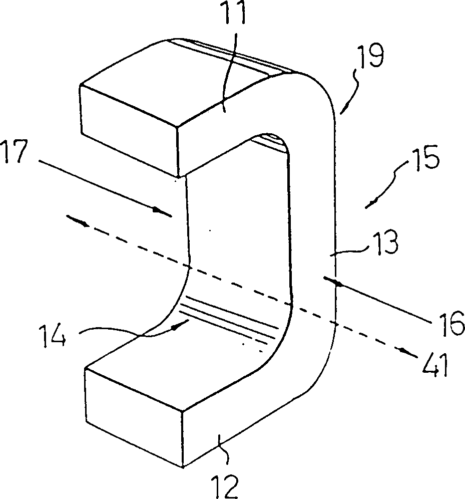
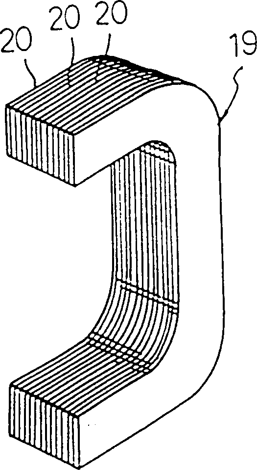
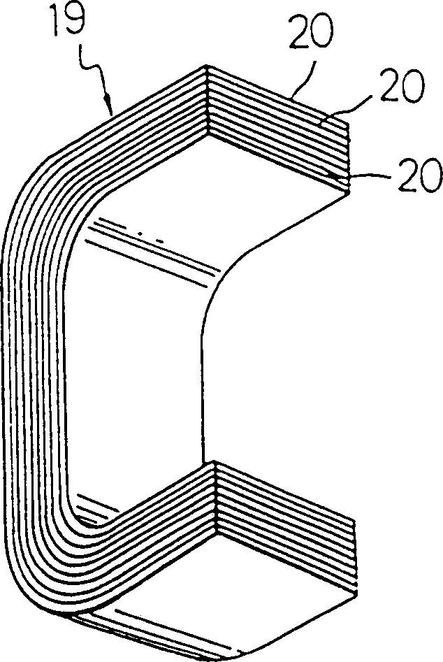
[0042] Please refer to FIG. 4 , which shows a basic form of a stator 90 for a motor or generator according to the present invention. This embodiment has three stator units 10 , wherein the stator unit 10 mainly includes a columnar body 19 and a coil 30 . For column 19, please also refer to figure 1 , for the convenience of the following description, the more detailed definition of the columnar body 19 is as follows. The columnar body 19 extends longitudinally from its top side 16 to its bottom side 17, the extending direction is defined as the longitudinal axis 41, and the columnar body 19 is roughly divided into a first end zone 11, a second end zone 12 and a middle section Zone 13, wherein the first end zone 11 and the second end zone 12 are respectively connected to both sides of the middle zone 13 (the N pole and the S pole are formed after the coil is wound and energized), and approach the inner side 14 of the monomer 10, and the inner side The opposite side of 14 forms...


PUM


Abstract

The stator unit used in the motor or generator of the present invention is roughly cylindrical, and is roughly divided into a first end area, a second end area and a middle section area, wherein the first and second end areas are connected on both sides of the middle section area, and Approaching toward the side of the monomer; wherein a plurality of stator monomers are neatly arranged around a central axis, and the longitudinal axis of each stator monomer is parallel to, perpendicular to, or even at an angle to the central axis.

Description

technical field [0001] The present invention relates to a motor or a generator, in particular to a stator applied to a motor or a generator. Background technique [0002] see Figure 20 , the known stator 80 used in motors or generators is formed by stacking and riveting iron sheets 81 with a thickness of about 0.5mm-0.35mm one by one. The iron sheets 81 have a plurality of teeth 82, a plurality of slots 83 and A hollow slot ring 84. This kind of conventional stator 80 produces a lot of residual waste (the part of the slot 83) during the manufacture, and the winding is complicated, so a coil winding machine and a shaping machine with high cost and complicated procedures are required. Wire binding machinery, etc., the investment equipment is complex and expensive, and there is not much room for flexibility in design. For example, when the number of poles (N poles and S poles) increases, coil winding is more difficult and the number of turns is reduced. Therefore, it is neces...

Claims


Application Information

Patent Timeline
Patent Type & Authority Patents(China)
IPC IPC(8): H02K1/14H02K3/18
Inventor 范扬锋
Owner 范扬锋
Why Eureka
Try Eureka