Encoder, motor and driving system

An encoder and code disc technology, applied in the encoder field, can solve the problem of high production cost, improve efficiency, solve the complex process of measuring position information, and simplify complex procedures.

Pending Publication Date: 2021-11-30
深圳市灵犀自动化技术有限公司
View PDF0 Cites 0 Cited by
  • Summary
  • Abstract
  • Description
  • Claims
  • Application Information

AI Technical Summary

Problems solved by technology

[0010] The main purpose of the present invention is to provide an encoder, a motor and a drive system to solve the problem of relatively high production costs of the optical-magnetic hybrid encoder in the prior art for measuring position information through three magnetic inductive chips

Method used


Image

  • Encoder, motor and driving system
  • Encoder, motor and driving system

Examples


Embodiment 1

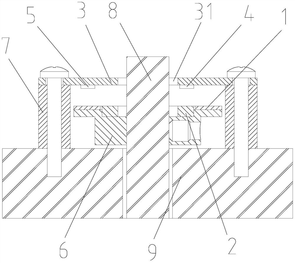
[0040] In the present embodiment, the encoder of the present invention, includes: the code disk 1 and magnet or magnetic ring 2, the code tray 1 and the magnetic steel or magnetic ring 2 are mounted on the rotor of the motor and synchronously with the rotor; circuit board 3 Including at least one magnetic sensing module 4, at least one light sensing module 5, and signal processing module, the magnetic sensing module 4 corresponds to the magnetic steel or magnetic ring 2, the light sensing module 5 is set corresponding to the code disk 1; wherein the encoder is also Including the encoder base 9, the encoder base 9 is mounted on the rear end cover of the motor, and the circuit board 3 is fixed to at least one first mounting portion provided on the encoder base 9.

Embodiment 2

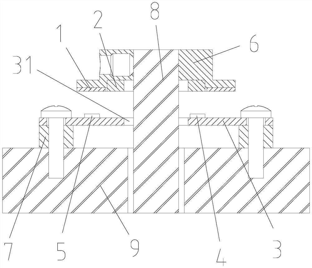
[0042] This embodiment differs from the embodiment of the embodiment in the mounting position of the circuit board 3, in the present embodiment, the encoder of the present invention, including: code disc 1 and magnetic steel or magnetic ring 2, code disc 1 and magnet steel Or the magnetic ring 2 is mounted on the rotor of the motor and moves synchronously with the rotor; the circuit board 3 includes at least one magnetic module 4, at least one light sensing module 5 and the signal processing module, magnetic module 4 and magnet or magnetic ring 2 Corresponding setting, the light sensing module 5 is set corresponding to the code disk 1; wherein the encoder further includes a rear end cap, a rear end cap and a rear end cover of the encoder base 9 or the motor, and a rear end cover for the motor. The disk 1, magnet or magnetic ring 2 and the receiving space of the circuit board 3 are fixed to at least one second mounting portion provided on the rear end cover of the encoder.

Embodiment 3

[0044] The difference from the first and seconds of the present embodiment is different from the mounting position of the circuit board 3, in the present embodiment, the encoder of the present invention, including: the code disc 1 and magnetic steel or magnetic ring 2, the code disc 1 and Magnetic steel or magnetic ring 2 is mounted on the rotor of the motor and moves synchronously with the rotor; the circuit board 3 includes at least one magnetic module 4, at least one light sensing module 5 and the signal processing module, magnetic module 4 and magnet or magnetic The ring 2 corresponds to the setting, the light sensing module 5 corresponds to the code disk 1; wherein the encoder is mounted on the rear cover of the motor, and the circuit board 3 is fixed to at least one third mounting portion provided on the rear end cover of the motor. .


PUM


Abstract

The invention provides an encoder, a motor and a driving system. The encoder is installed on the motor. The encoder comprises a code disc and magnetic steel or a magnetic ring, and the code disc and the magnetic steel or the magnetic ring are installed on a rotor of the motor and synchronously move along with the rotor; the circuit board comprises at least one magnetic induction module, at least one light induction module and a signal processing module, the magnetic induction module is arranged corresponding to the magnetic steel or the magnetic ring, and the light induction module is arranged corresponding to the code disc; the circuit board is fixedly connected with at least one first mounting part arranged on the encoder base; or the circuit board is fixedly connected with at least one second mounting part arranged on the encoder rear end cover; or the circuit board is fixedly connected with at least one third mounting part arranged on the rear end cover of the motor. The encoder provided by the invention solves the problem that in the prior art, an optomagnetic hybrid encoder measures position information through three magnetic induction chips, and the production cost is relatively high.

Description

Technical field [0001] The present invention relates to the field of encoders, and in particular, to an encoder, a motor, and a drive system. Background technique [0002] Encoder technology is widely used in the field of precision instrument control and position detection such as motor speed measurement and position detection, such as absolute encoders can be used to detect the number of rotation of the motor, the rotation direction, and the rotational position. [0003] With the advancement of technology, in order to meet the precision, stability and cost of control systems, the accuracy requirements and reliability requirements of the encoder are getting higher and higher, and the installation conditions of the encoder need to be lower to reduce Installation cost. [0004] In the high-precision absolute value encoder, it is made in two ways to obtain a high-precision absolute value, wherein the absolute value coded is a rough channel, and the relative position code is used as ...

Claims


Application Information

Patent Timeline
Patent Type & Authority Applications(China)
IPC IPC(8): H02K11/215H02K11/22G01D5/56G01D5/58
Inventor 左思蓝维隆
Owner 深圳市灵犀自动化技术有限公司
Why Eureka
Try Eureka