Horizontal structure 3D printing system

A 3D printing and horizontal structure technology, applied in the field of architectural 3D printing, can solve the problems of limited printing shape, inability to realize the overall printing of horizontal structures, and printing can not be fully automated

Active Publication Date: 2021-01-05
SHANGHAI CONSTRUCTION GROUP
View PDF11 Cites 0 Cited by
  • Summary
  • Abstract
  • Description
  • Claims
  • Application Information

AI Technical Summary

Problems solved by technology

[0005] The present invention aims to invent a horizontal structure 3D printing system, which provides a supporting load-bearing mechanism for a mobile 3D printing robot through an external support structure so as to provide a printing space compatible with the printing structure, and through a free follow-up template device fixed to the external support structure Dynamically adjust the movement to provide a bottom support platform for horizontal structure printing, and complete the printing and construction of the horizontal structure through the mobile 3D printing robot collaborative printing job, solving the problem that the existing 3D printing device and method cannot realize the overall printing of the horizontal structure, and the printing cannot be fully automated. Horizontal structure printing is limited by the printing shape of materials, etc., to achieve efficient, safe and automatic construction of horizontal structures

Method used


Image

  • Horizontal structure 3D printing system
  • Horizontal structure 3D printing system
  • Horizontal structure 3D printing system

Examples


Embodiment Construction

[0027] The present invention will be described in further detail below in conjunction with the accompanying drawings and specific embodiments. The technical content and features of the present invention will be described in detail below by referring to the illustrated embodiments in conjunction with the accompanying drawings. It should be further noted that all the drawings are in very simplified form and use imprecise scales, and are only used to facilitate and clearly assist the purpose of illustrating the embodiments of the present invention. For the convenience of description, the "up" and "down" described below are consistent with the directions of up and down in the drawings, but this should not be a limitation of the technical solution of the present invention.

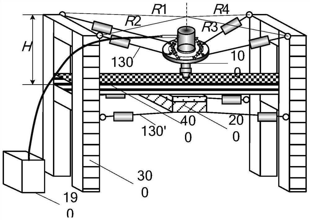
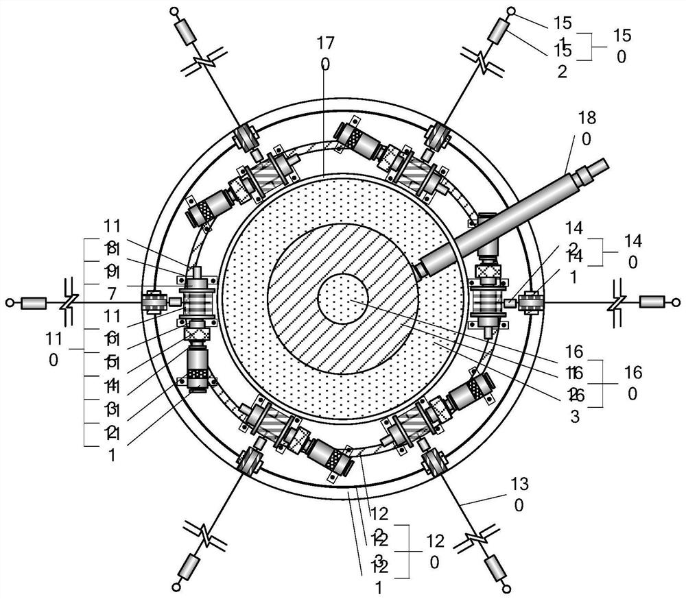
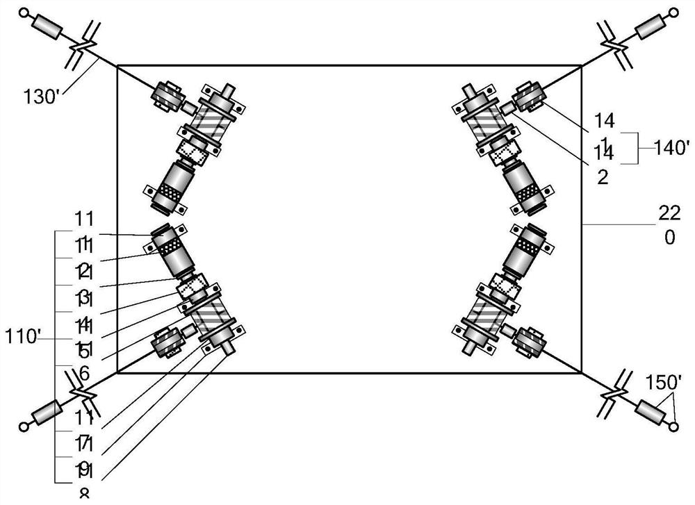
[0028] see Figure 1 to Figure 5 , this embodiment discloses a horizontal structure 3D printing system, including a mobile 3D printing robot 100, a free-following template device 200 and an external support st...


PUM


Abstract

The invention provides a horizontal structure 3D printing system. The system adopts a mobile 3D printing robot, a free follow-up template device and an external support structure, and the mobile 3D printing robot comprises a plurality of first rope driving guide mechanisms, a mobile platform, a printing head mechanism and a printing head connecting mechanism; each first rope driving guide mechanism comprises a first rope driving and braking mechanism, a first high-strength rope, a first rope guiding mechanism and a first fixing assembly, and accurate printing and positioning of the mobile platform are achieved by taking up and paying off the first high-strength rope through the first rope driving and braking mechanism; the free follow-up template device comprises a plurality of second ropedriving guide mechanisms and a follow-up platform, and each second rope driving guide mechanism comprises a second rope driving brake mechanism, a second high-strength rope, a second rope guide mechanism and a second fixing assembly; and the second rope driving brake mechanism winds and unwinds the second high-strength ropes to realize accurate positioning of the follow-up template. The system has the advantages of light dead weight, small size, convenience in mounting and high automation degree.

Description

technical field [0001] The invention belongs to the technical field of architectural 3D printing, and in particular relates to a horizontal structure 3D printing system. Background technique [0002] The degree of mechanization and automation of the traditional construction industry is low, and its development urgently needs transformation and upgrading. With the development and maturity of 3D printing technology, this technology will bring technological innovation to the labor-intensive construction industry. Architectural 3D printing technology has the characteristics of high degree of mechanization and automation, one-time molding, less construction consumables and process loss, etc. Way, its research has become the development trend of the construction industry. [0003] The 3D printing construction of long-span horizontal structures is one of the biggest challenges of architectural 3D printing. Due to the limitations of materials and devices, and the inability of hori...

Claims


Application Information

Patent Timeline
Patent Type & Authority Applications(China)
IPC IPC(8): E01D21/00E04G21/00E04G21/04B33Y30/00
CPCE01D21/00E04G21/00E04G21/04B33Y30/00
Inventor 左自波黄玉林张龙龙杜晓燕
Owner SHANGHAI CONSTRUCTION GROUP
Why Eureka
Try Eureka