Stage constant-speed ascending and descending device and control method thereof

A lifting device and stage technology, which is applied in the field of stage lifting, can solve the problems of large thickness of the supporting surface of the stage, no guardrails, and restrictions on the use of the stage, and achieve the effects of increasing applicability, ensuring safety, and good practicability

Active Publication Date: 2021-01-05
马鞍山宏博电子科技有限公司
View PDF8 Cites 2 Cited by
  • Summary
  • Abstract
  • Description
  • Claims
  • Application Information

AI Technical Summary

Problems solved by technology

[0003] At present, when the existing stage is raised and lowered, the stage is ejected from the supporting surface of the stage. The vertical take-off and landing of the stage requires a large sliding interval on the supporting surface at the bottom of the stage. This setting will make the supporting surface of the stage The thickness is relatively large, which restricts the use of the stage, and the existing stage lifting device does not have a protective fence for easy use

Method used


Image

  • Stage constant-speed ascending and descending device and control method thereof
  • Stage constant-speed ascending and descending device and control method thereof
  • Stage constant-speed ascending and descending device and control method thereof

Examples


Embodiment 1

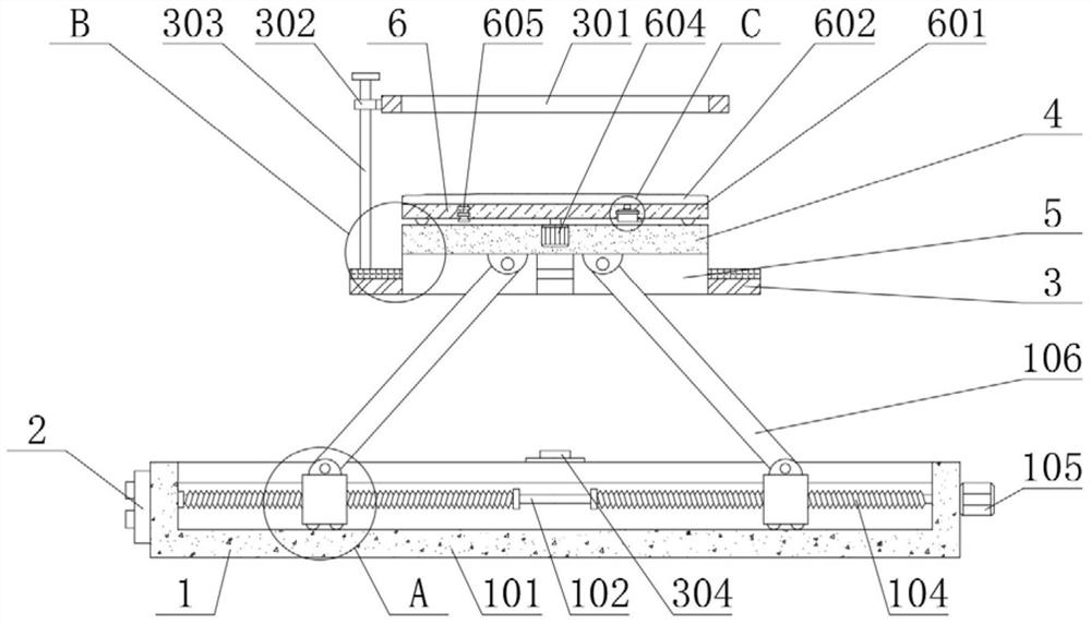
[0029] see Figure 1-6 , the present invention provides a technical solution:

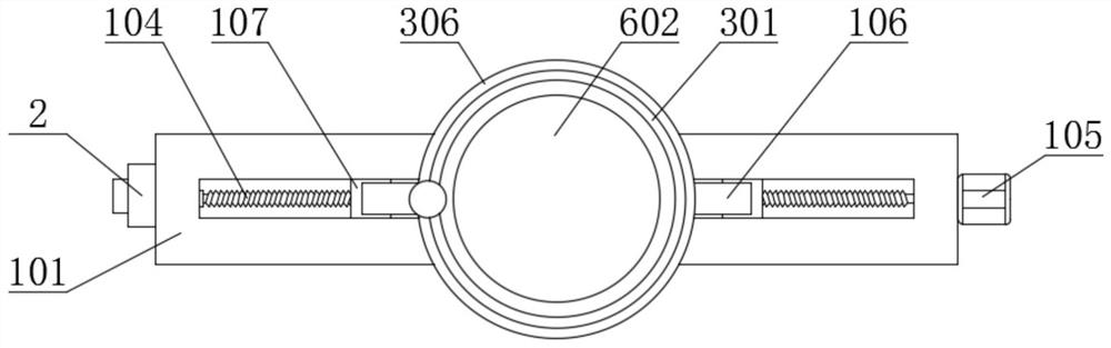
[0030] The stage uniform lifting device includes a support plate 4 and a controller 2. The bottom end of the support plate 4 is provided with a lifting mechanism 1, and the bottom end of the support plate 4 is fixedly connected with a limit plate 5, which acts as a limit. , the lifting mechanism 1 includes a support surface 101, the right end of the support surface 101 is fixedly connected with a first motor 105, the end of the main shaft of the first motor 105 is fixedly connected with a rotating rod 102, and the left and right sides of the rotating rod 102 are fixedly connected with threads 104, The directions of the threads 104 on the left and right sides are opposite, and the outer sides of the threads 104 are spirally connected with a slide block 107, and the top of the slide block 107 is connected with a connecting rod 106 through a hinge, and the top of the connecting rod 106 and the bottom ...

Embodiment 2

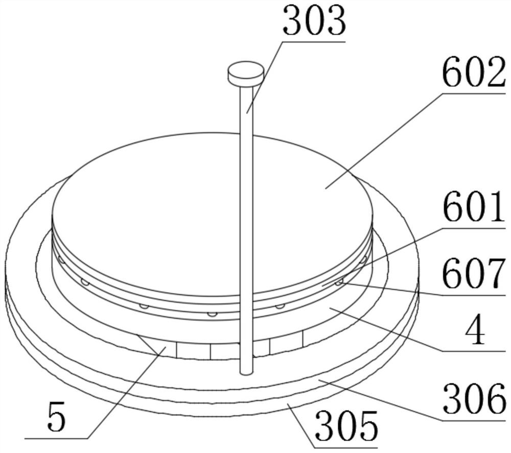
[0034] Workflow: In Embodiment 2, the same parts as Embodiment 1 will not be repeated. The difference is that when the performers feel that the inflatable air cushion 602 is hard and will affect their performance, they can control the solenoid valve 605 to open through the controller 2. The electromagnetic valve 605 is opened, and the air inside the inflatable air cushion 602 will be discharged, and the top surface of the inflatable air cushion 602 will become soft due to the reduction of internal pressure, so as to meet the needs of performers, and has good practicability. The controller 2 controls the motor 105 to reverse, the motor 105 drives the rotating rod 102 to rotate, and the rotating rod 102 drives the threads 104 on both sides to rotate, because the directions of the threads 104 on both sides of the rotating rod 102 are opposite, and the threads 104 on both sides will respectively drive The slide block 107 on the outside is separated, and during the process of separa...


PUM


Abstract

The invention relates to the technical field of stage ascending and descending, in particular to a stage constant-speed ascending and descending device. The stage constant-speed ascending and descending device comprises a supporting disc and a controller, an ascending and descending mechanism is arranged at the bottom end of the supporting disc, a limiting plate is fixedly connected with the bottom end of the supporting disc, the ascending and descending mechanism comprises a supporting face, a first motor is fixedly connected with the right end of the supporting face, and the tail end of a main shaft of the first motor is fixedly connected with a rotating rod. According to the stage constant-speed ascending and descending device, ascending and descending of a stage can be achieved throughthe arranged components such as a supporting face, threads and a connecting rod, the ascending and descending mode does not need the supporting face to prestore the ascending and descending height, the stage ascending and descending applicability is improved, the motor drives the rotating rod to rotate, the rotating rod drives the threads on the two sides to rotate, due to the fact that the directions of the threads on the two sides of the rotating rod are opposite, the threads on the two sides can drive sliding blocks on the outer sides to be close to or separated from each other, the connecting rod tends to be perpendicular or parallel on the supporting face, the supporting disc can ascend or descend, and stage ascending and descending are achieved.

Description

technical field [0001] The invention relates to the field of stage lifting technology, in particular to a stage constant speed lifting device and a control method thereof. Background technique [0002] The stage is the space provided for actors to perform in the theater. It can make the audience's attention focus on the actor's performance and obtain the ideal viewing effect. The stage is usually composed of one or more platforms. The types of the stage include frame stage, stretching stage, ring stage and revolving stage. [0003] At present, when the existing stage is raised and lowered, the stage is ejected from the supporting surface of the stage. The vertical take-off and landing of the stage requires a large sliding interval on the supporting surface at the bottom of the stage. This setting will make the supporting surface of the stage The thickness is relatively large, which restricts the use of the stage, and the existing stage lifting device does not have a protect...

Claims


Application Information

Patent Timeline
Patent Type & Authority Applications(China)
IPC IPC(8): E04H3/24E04H3/26G05B19/04
CPCE04H3/24E04H3/26G05B19/04
Inventor 汪训敏
Owner 马鞍山宏博电子科技有限公司
Why Eureka
Try Eureka