Rectifying blade body end face position measuring device and method

A technology of rectifying blade and measuring device, applied in measuring device, mechanical measuring device, using mechanical device and other directions, can solve problems such as batch out of tolerance, and achieve the effect of simple structure, simple operation and improved inspection accuracy

Inactive Publication Date: 2021-01-05
AECC AVIATION POWER CO LTD
View PDF13 Cites 0 Cited by
  • Summary
  • Abstract
  • Description
  • Claims
  • Application Information

AI Technical Summary

Problems solved by technology

[0003] The purpose of the present invention is to provide a device and method for measuring the position of the end surface of the rectifying blade blade body, so as to solve the problem that the gap between the end surface of the blade body and the casing and the inner ring is out of tolerance in batches after the blade is installed. Accurately measure the actual value at each position of the end surface of the airfoil to improve the inspection accuracy of the parts

Method used


Image

  • Rectifying blade body end face position measuring device and method
  • Rectifying blade body end face position measuring device and method
  • Rectifying blade body end face position measuring device and method

Examples


Embodiment Construction

[0033] Below in conjunction with accompanying drawing, the present invention is described in further detail:

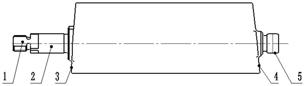
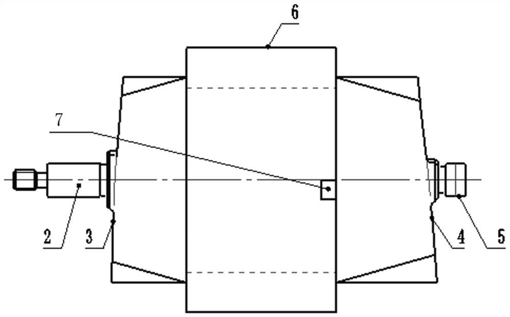
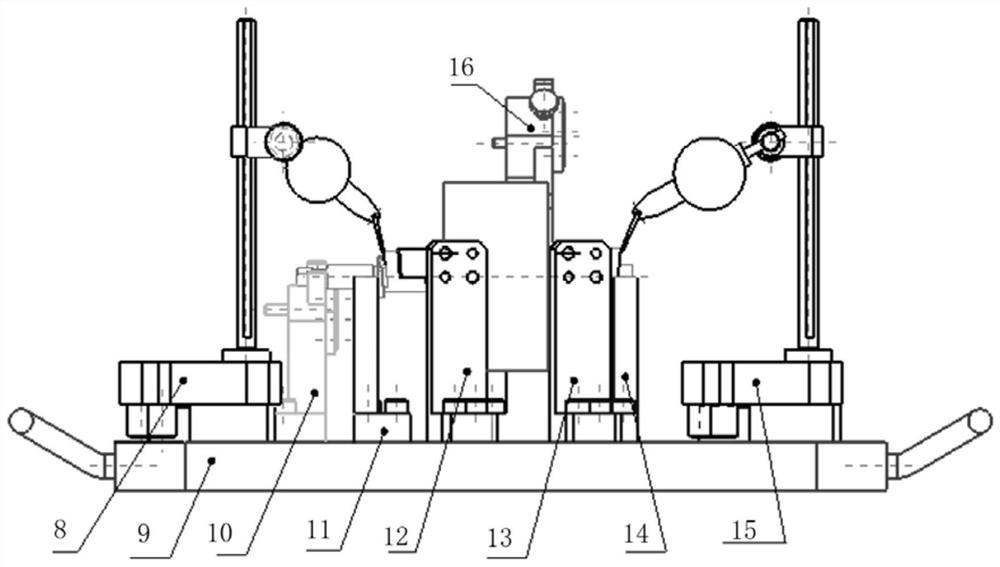
[0034] see Figure 1 to Figure 10 , a device for measuring the position of the airfoil end surface of a rectifying blade, comprising a first positioning V-shaped block 11 and a second positioning V-shaped block 14 for positioning the upper journal 2 and the lower journal 5 of the rectifying blade respectively, said The first positioning V-shaped block 11 and the second positioning V-shaped block 14 are used to limit the deviation of the rectifying blades in the X, Y, and Z directions and the twisting around the Y and Z directions, and also include a device for limiting the twisting of the rectifying blades around the X direction. Positioning means.

[0035] When the side of the upper journal 2 of the rectifier blade is provided with a mounting flat 1, the positioning device adopts the upper journal positioning device arranged between the first positioning V-shaped bl...


PUM


Abstract

The invention discloses a rectifying blade body end face position measuring device and method, and the device comprises a first positioning V-shaped block and a second positioning V-shaped block whichare respectively used for positioning an upper shaft neck and a lower shaft neck of a rectifying blade, and also comprises a positioning unit; an upper shaft neck side blade body end face limiting block and a lower shaft neck side blade body end face limiting block are arranged on the outer side of the first positioning V-shaped block and the outer side of the second positioning V-shaped block respectively and connected with a first gauge stand and a second gauge stand respectively in a matched mode; the upper sides of the first gauge stand and the second gauge stand are respectively connected with dial gauges used for measuring an upper shaft neck side blade body end face and a lower shaft neck side blade body end face, an upper shaft neck side blade body end face gauge checking member and a lower shaft neck side blade body end face gauge checking member are arranged between the upper shaft neck side blade body end face limiting block and the lower shaft neck side blade body end facelimiting block.

Description

technical field [0001] The invention belongs to the technical field of engine rectifying blade measurement, and in particular relates to a device and method for measuring the position of a rectifying blade blade body end surface. Background technique [0002] With the development of my country's aviation industry, the performance requirements of the engine are also increasing, and the gap between the end face of the blade body and the casing and the inner ring increases, which reduces the performance of the engine. The size of the end surface of the blade airfoil is the main factor affecting the clearance between the engine blade and the casing and the inner ring, and it is particularly important to control the position of the end surface of the blade airfoil. The end face of the airfoil is a spatial conical surface, and the accuracy requirements for position size and surface roughness are getting higher and higher. The first common measurement method is to use a template t...

Claims


Application Information

Patent Timeline
Patent Type & Authority Applications(China)
IPC IPC(8): G01B5/00G01B5/14
CPCG01B5/00G01B5/0004G01B5/003G01B5/14
Inventor 刘金凤梁忠效郭海杜家燕张楠高峰利
Owner AECC AVIATION POWER CO LTD
Why Eureka
Try Eureka