Resistance measuring instrument and resistance measuring method

A resistance measuring instrument and resistance technology, applied in the field of measurement, can solve the problems of large leakage current of electronic switches, large changes with temperature, low measurement result accuracy, etc., and achieve the effect of simple circuit structure and improved measurement accuracy.

Pending Publication Date: 2017-07-28
江南工业集团有限公司
View PDF10 Cites 7 Cited by
  • Summary
  • Abstract
  • Description
  • Claims
  • Application Information

AI Technical Summary

Problems solved by technology

[0004] First, the forward current value and reverse current value generated by the bidirectional constant current source must be strictly equal, otherwise the resistance measurement accuracy will be low
[0005] Second, the electronic switch is used to switch the current direction of the bidirectional constant current source. Due to the large leakage current of the electronic switch and the large change with temperature, it brings great uncertainty to the test results and the accuracy of the measurement results is low.
[0006] Third, the reference source used by the bidirectional constant current source and AD converter is easily affected by temperature, thus affecting the test results; in addition, the voltage acquisition and amplifier drift will also affect the test results
When this resistance measuring instrument is used in a wide temperature field, the temperature will have a great influence on the test results. Because the temperature drift is affected by many factors, it has great uncertainty, and it is impossible to use a computer for temperature compensation. The accuracy of the measurement results Low

Method used


Image

  • Resistance measuring instrument and resistance measuring method
  • Resistance measuring instrument and resistance measuring method

Examples


Embodiment Construction

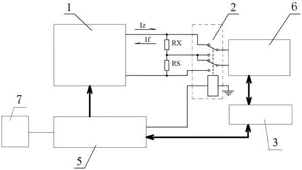
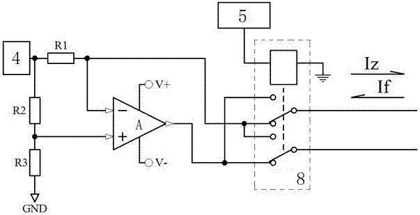
[0026] Such as figure 1 and figure 2 As shown, the resistance measuring instrument includes a bidirectional constant current source 1, a voltage acquisition and amplifier 6, and an AD converter 3. Its structural feature is that the bidirectional constant current source 1, the standard resistance Rs and the measured resistance Rx are connected into a series circuit, and the voltage The output end of the acquisition and amplifier 6 is electrically connected to the controller 5 through the AD converter 3, and the controller 5 is electrically connected to the display terminal 7, and also includes a control voltage acquisition and the amplifier 6 is connected to the two ends of the standard resistance Rs or is connected to the standard resistor Rs. The switch module at both ends of the measuring resistance Rx, the controller 5 is electrically connected to the control terminal of the switch.

[0027] The switch module includes a first double-pole double-throw relay 2 , and the con...


PUM


Abstract

The invention discloses a resistance measuring instrument and a resistance measuring method, wherein the resistance measuring instrument comprises a bidirectional constant current source, a voltage acquisition and amplifying device, an AD converter, a bidirectional constant current source, a series loop composed of a standard resistor and a measured resistor. The voltage acquisition and amplifying device is electrically connected with a controller through the AD converter, and the controller and the display terminal are electrically connected. The resistance measuring instrument also comprises a switching switch module used for controlling the voltage acquisition and amplifying device to be connected at two ends of the standard resistor or two ends of the measured resistor, and the controller is electrically connected with the control end of a switching switch. The circuit structure is simple, and the positive and negative constant current values generated by the bidirectional constant current source need not be strictly equal, which reduces the requirement for the hardware precision. The leakage current of the electronic switch is prevented from influencing the measurement precision. The temperature drift of the measurement result only relates to the temperature drift of the standard resistor, and the standard resistor of the low temperature drift is selected to improve the measurement precision under the wide temperature range condition of the instrument. The influences of oriented interference on the measurement result can be eliminated.

Description

technical field [0001] The invention belongs to the technical field of measurement, in particular to a resistance measuring instrument and a resistance measuring method. Background technique [0002] At present, the resistance measuring instrument used to measure the resistance of pyrotechnics using the principle of the small current bidirectional test method includes a bidirectional constant current source, a voltage acquisition and amplifier, and an AD converter. When measuring, first use a bidirectional constant current source to generate a forward (reverse) current, and pass the forward (reverse) current through the measured resistance. Then use the voltage acquisition and amplifier and AD converter to measure the forward (reverse) voltage on the measured resistance, and divide the measured forward (reverse) voltage by the known forward (reverse) current value , get the forward resistance value and reverse resistance value of the measured resistance. Finally, the measu...

Claims


Application Information

Patent Timeline
Patent Type & Authority Applications(China)
IPC IPC(8): G01R27/14
CPCG01R27/14
Inventor 尹波吴松延尹屹杨哲马敏张炳坤刘凡
Owner 江南工业集团有限公司
Why Eureka
Try Eureka