Time-grating linear displacement sensor

A linear displacement and sensor technology, applied in instruments, measuring devices, electrical devices, etc., can solve the problems of complex sensor structure, low precision, and complicated excitation coil windings.

Active Publication Date: 2015-08-19
CHONGQING UNIV OF TECH
View PDF5 Cites 7 Cited by
  • Summary
  • Abstract
  • Description
  • Claims
  • Application Information

AI Technical Summary

Problems solved by technology

However, if it is necessary to further improve its resolution, it can only be achieved by reducing the spatial pole distance or increasing the number of pole pairs of the sensor, which is expensive.
[0003] CN103644834A discloses a time grating linear displacement sensor, which can double the measurement resolution of the time grating linear displacement sensor without increasing the accuracy of the engraved line or the number of sensor poles, but the excitation of the sensing unit The coil is composed of a plurality of forward-wound planar re

Method used


Image

  • Time-grating linear displacement sensor
  • Time-grating linear displacement sensor
  • Time-grating linear displacement sensor

Examples


Embodiment 1

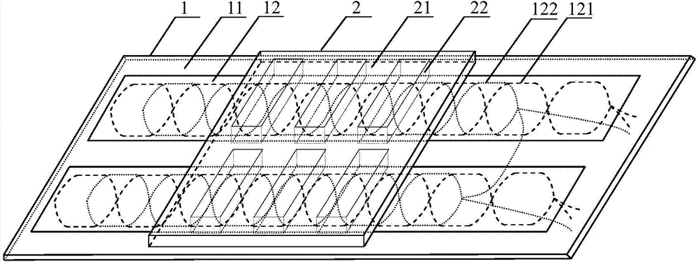
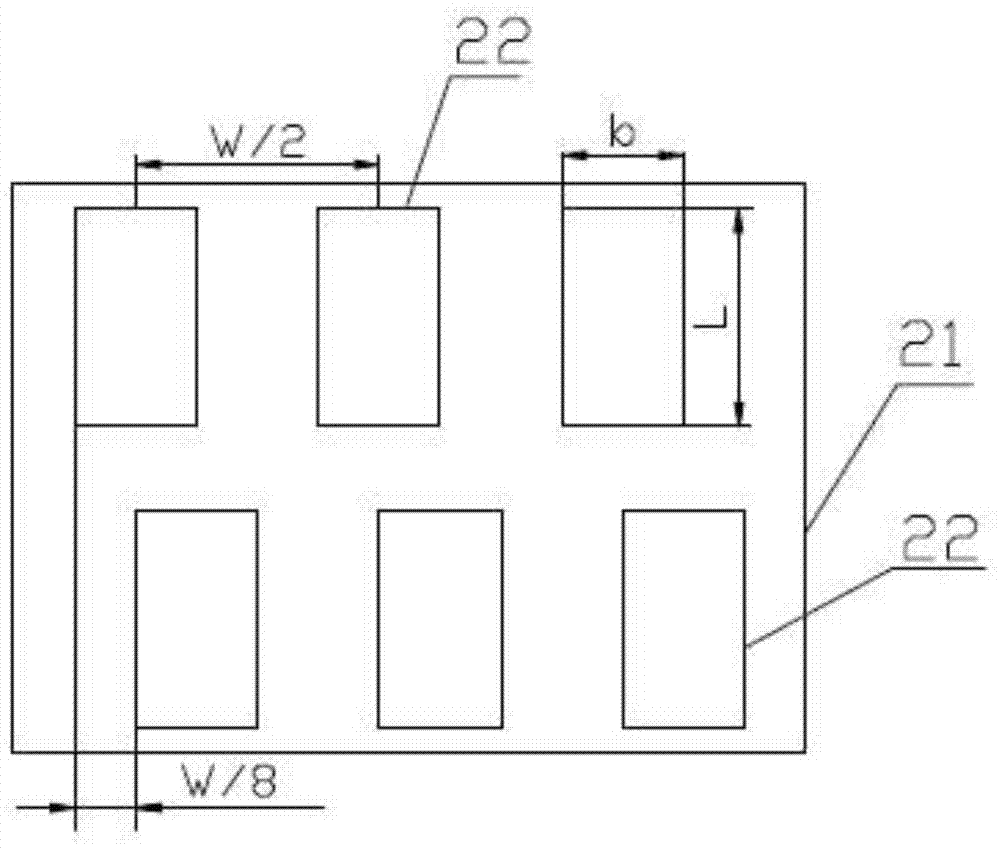
[0027] Embodiment 1: as Figure 1 to Figure 4 The time grating linear displacement sensor shown includes fixed scale 1 and moving scale 2.

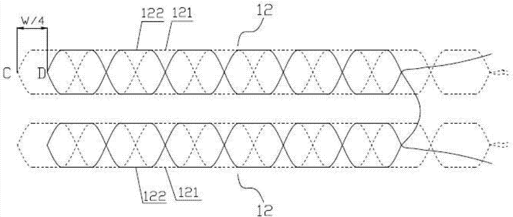
[0028] The fixed length 1 is composed of a fixed length matrix 11 and two identical and parallel sensing units 12 that do not interfere with each other. The distance between the two sensing units 12 is equal to 10 mm. The fixed length matrix 11 is a rectangular parallelepiped iron matrix. Taking the long side direction of the fixed-length substrate 11 as the measurement direction, the sensing unit 12 includes an excitation coil 121 and an induction coil 122. The excitation coil 121 and the induction coil 122 adopt a printed circuit wiring method, and are independently arranged on different parts of the printed circuit board. On the wiring layer, two sets of printed circuit boards with excitation coils 121 and induction coils 122 are fixed parallel to each other on the upper and lower parts of the surface of the scale substrate 11 to form ...

Embodiment 2

[0044] Embodiment 2: as Figure 5 to Figure 7 The time grating linear displacement sensor shown, most of its structure is the same as that of Embodiment 1, the difference is that: the starting position of the exciting coil 121 of the sensing unit 12 on the upper part of the fixed-length substrate 11 is aligned with the fixed-length substrate 11 along the measurement direction. The initial position of the excitation coil 121 of the sensing unit 12 of the bottom is apart from S (S is not equal to 0), and the initial position of the induction coil 122 of the sensing unit 12 of the upper part of the fixed-length substrate 11 is along the measurement direction and the lower part of the fixed-length substrate 11. The initial positions of the induction coils 122 of the sensing unit 12 are separated by S (S is not equal to 0). The initial position of the magnetic conductor 22 embedded in the magnetic conduction unit at the upper part of the dynamic scale base 21 is far from the initia...

Embodiment 3

[0052] Embodiment 3: Most of its structure is the same as that of Embodiment 1, the difference is that the magnetic conduction unit is composed of a rectangular parallelepiped magnetic conduction body 22; Inside.


PUM


Abstract

The invention discloses a time-grating linear displacement sensor, and the sensor comprises a fixed ruler which consists of a fixed ruler base body and two sensing units, and also comprises a moving ruler which consists of a moving ruler base body and two magnetic conduction units. Each sensing unit comprises an excitation coil and an induction coil, wherein the induction coil starts at a zero point, and two ends of the induction coil are wound along two staggered piecewise functions to form N 90-degree inverted 8-shaped continuous winding tracks, wherein the period of the piecewise functions is W. The winding mode of the induction coils is the same as the winding mode of the excitation coils, and the winding tracks of the induction coils are curves of the winding tracks of the excitation coils after the winding tracks of the excitation coils move by W/4 towards the right in the measurement direction. The induction coils of the two sensing units are in series connection. Each magnetic conduction unit is formed by the arrangement of a plurality of magnetizers in the measurement direction at equal intervals, and the center distance of two adjacent magnetizers is equal to W/2. The width b and length L of each magnetizer meet a specific condition, and the starting positions of magnetizers in two magnetic conduction units meet a specific condition. The sensor can prevent the turns of the excitation coils and the distribution condition of all coils from affecting the measurement precision.

Description

technical field [0001] The invention belongs to the technical field of precision measurement sensors, and in particular relates to a time grating linear displacement sensor. Background technique [0002] Precision linear displacement measurement usually uses various types of linear displacement sensors, such as gratings, toothed gratings, capacitive gratings, etc. They mainly improve the measurement resolution through two ways: one is to increase the density of space characterization and reduce the space grating; the other is to increase the electronic subdivision multiple. In recent years, a time-grid linear displacement sensor based on the principle of electromagnetic induction has appeared. Different from the above-mentioned linear displacement sensor, the time-grid linear displacement sensor uses clock pulses as the measurement reference, so its resolution depends on the spatial pole distance of the sensor on the one hand. On the other hand, it also depends on the space...

Claims


Application Information

Patent Timeline
IPC IPC(8): G01B7/02
Inventor 陈锡侯鲁进汤其富武亮
Owner CHONGQING UNIV OF TECH
Why Eureka
Try Eureka