Non contact optical digital guide extension meter

A non-contact, extensometer technology, applied in the direction of material analysis, scientific instruments, measuring devices, etc. by optical means, can solve the problems of measurement accuracy, influence measurement accuracy, complicated auxiliary equipment, etc., to solve permanent damage, Ease of use and high precision

Inactive Publication Date: 2006-01-11
SHOUGANG CORPORATION
View PDF3 Cites 7 Cited by
  • Summary
  • Abstract
  • Description
  • Claims
  • Application Information

AI Technical Summary

Problems solved by technology

This type of extensometer has a fixed gauge length and cannot adapt to the different requirements for the gauge length in material testing. The usual practice is to prepare extensometers with various gauge lengths, which increases the number and complexity of spare parts for the test equipment
This type of extensometer must be mechanically connected to the test piece, and the vibration and temperature changes of the test piece will affect the measurement accuracy
This type of extensometer converts the deformation of the test piece into a weak analog signal. It must be equipped with a high-precision, high-gain analog signal amplification device. In order to cooperate with computer data acquisition and control, it must also be equipped with an analog / digital conversion device. Auxiliary equipment complex
Temperature drift and zero point drift, as well as the mechanical gap of the mechanical connection affect the measurement accuracy, especially the accidental fracture and bending deformation of the specimen during the test will also cause permanent damage to the extensometer that is mechanically connected to it

Method used


Image

  • Non contact optical digital guide extension meter
  • Non contact optical digital guide extension meter
  • Non contact optical digital guide extension meter

Examples


Embodiment Construction

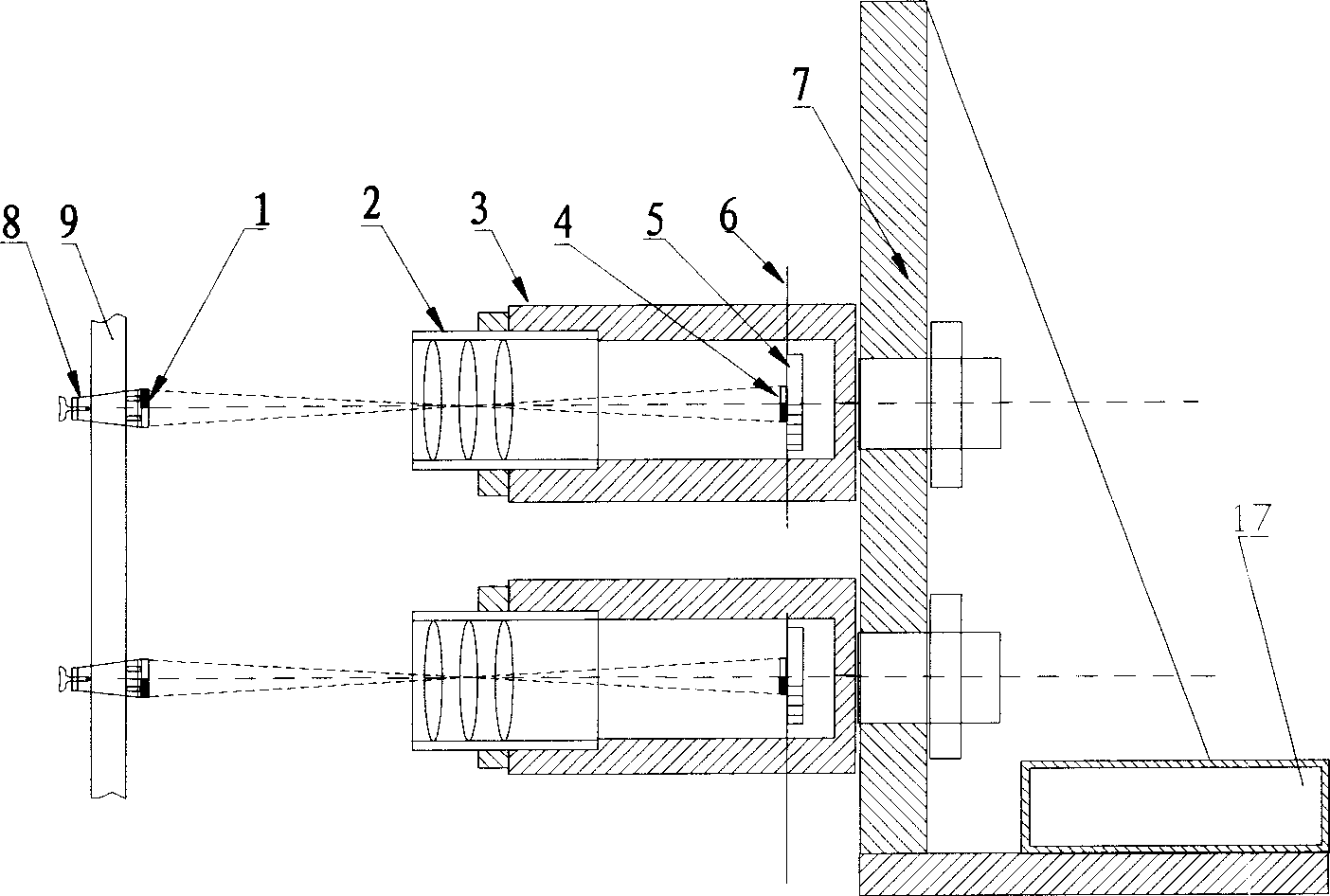
[0018] exist figure 1 Among them, the fastening device 8 fixes two reflective marks 1 with black and white patterns on the two ends of the gauge length of the test piece 9 respectively, connects the lens group 2 with the imager 3, and fixes the image sensor linear array 5 on the imager 3 Inside, the lens group 2 and the imager 3 are connected by thread, so that the distance between the lens and the image sensor linear array 5 can be adjusted. Make the image of the retroreflective mark on the image plane 6 of the image sensor linear array 5 .

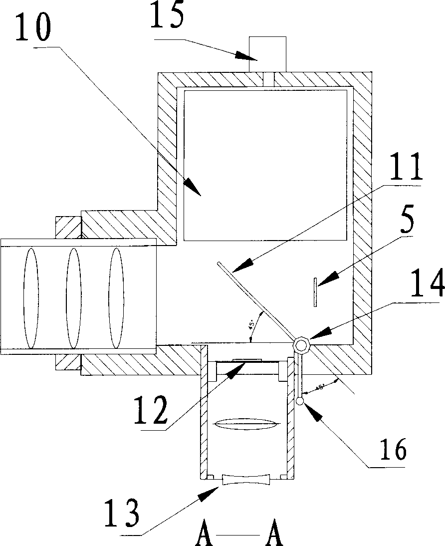
[0019] exist image 3 In the process, the circuit board 10 is installed in the imager 3 , one end of the circuit board is connected to the image sensor linear array 5 , and the other end is connected to the signal connector 15 . The movable plane mirror flap 11 is placed between the lens group 2 and the image sensor linear array 5, and is connected with the imager via the rotating shaft 14. When the connecting line of the plane mirror...


PUM


Abstract

The present invention relates to a non-contact optical digital tensiometer. It is composed of two groups of optical lens, two imagers, two linear image sensors, comparison logic and counting circuit, clock pulse generator, microcontroller and two reflecting marks fixed on the sample to be measured. Said invention also provides its working principle and application method.

Description

technical field [0001] The invention belongs to a device for measuring tensile and compressive deformation of a test piece in material mechanics, in particular to a device for measuring the small deformation of a test piece in the mechanical performance test of metal materials and some non-metallic materials. Belongs to the category of measuring devices. technical background [0002] The extensometer is an important part of the material testing machine. It is used to measure the small deformation of the tested piece in the state of tension, compression, vibration and fracture. The extensometer is required to have high precision, high reliability, high sensitivity and shock resistance. Currently known to use resistance strain gauge extensometer and photoelectric extensometer and contact measurement, for example: Chinese patent ZL93219143.6 resistance strain gauge extensometer, Chinese patent ZL92218236.1 unlimited photoelectric extensometer, Chinese patent ZL02115729.4 exten...

Claims


Application Information

Patent Timeline
Patent Type & Authority Applications(China)
IPC IPC(8): G01N3/06G01N3/00G01N21/84
Inventor 王永春
Owner SHOUGANG CORPORATION
Why Eureka
Try Eureka