
Eddy current damper for segment model testing, vibration device and experimental method

An eddy current damper and model testing technology, applied in the field of eddy current dampers and vibration devices for segment model testing, can solve problems such as vibration device errors

Pending Publication Date: 2021-01-05
CHANGAN UNIV
View PDF0 Cites 5 Cited by
  • Summary
  • Abstract
  • Description
  • Claims
  • Application Information

AI Technical Summary

Problems solved by technology

[0004] One of the objectives of the present invention is to provide a linear eddy current damper and a vibration device containing the linear eddy current damper, which solves the problem of errors in the current vibration device

Method used


Image

  • Eddy current damper for segment model testing, vibration device and experimental method
  • Eddy current damper for segment model testing, vibration device and experimental method
  • Eddy current damper for segment model testing, vibration device and experimental method

Examples


Embodiment Construction

[0049] The present invention will be further described in detail below in conjunction with specific embodiments, which are explanations of the present invention rather than limitations.

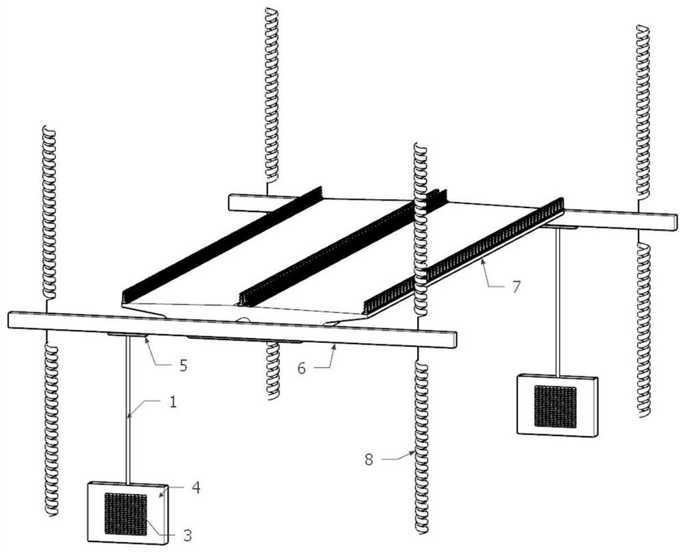
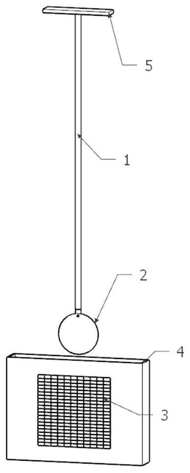
[0050] Such as figure 2 As shown, the present invention discloses a linear eddy current damper, comprising a rigid insulating rod 1, a metal sheet 2 and two permanent magnets 3; the lower end of the rigid insulating rod 1 is connected to the metal sheet 2; the two permanent magnets 3 are fixedly placed on Directly below the metal sheet 2, and the two permanent magnets 3 keep a distance, and the N level of one permanent magnet 3 is opposite to the S level of the other permanent magnet 3, forming an approximately uniform magnetic field.

[0051] More preferably, a fixed box 4 is arranged directly below the metal sheet 2, and two permanent magnets 3 are fixed on the front and rear panels of the fixed box 4, so that the position can be easily moved, as long as the fixed box 4 is moved.

[0052]...


PUM


Abstract

The invention relates to the technical field of pneumatic tests, and particularly discloses an eddy current damper for segment model testing, the linear eddy current damper is arranged at two ends ofa segment model and arranged diagonally, and the linear eddy current damper comprises a rigid insulating rod, a metal sheet and two permanent magnets; the lower end of the rigid insulating rod is connected with the metal sheet, and the upper end of the rigid insulating rod is connected with a suspension arm; the two permanent magnets are placed under the metal sheet, and a gap is kept between thetwo permanent magnets to form a magnetic field. The invention further discloses a vibration device which comprises a segment model, springs, two suspension arms and the linear eddy current damper, thesuspension arms are fixedly connected to the two ends of the segment model and are symmetrically arranged, the springs are connected to the upper portions and the lower portions of the two ends of each suspension arm respectively, and the other end of each of the springs is fixedly installed in a pneumatic laboratory. The upper end of the rigid insulating rod is detachably connected with the suspension arms, and the problem that an existing vibration device has errors is solved. The invention further discloses an experimental method based on the vibration device, and data support and great convenience are provided for testers.

Description

technical field [0001] The invention relates to the technical field of aerodynamic testing, in particular to an eddy current damper, a vibration device and an experimental method for segmental model testing. Background technique [0002] Since the phenomenon of vortex vibration occurred in Humen Bridge, the problem of vortex vibration of bridge structure has attracted widespread attention. In the current field of bridge wind engineering, the vortex vibration performance of structures often requires wind tunnel experiments for research. The coupled vibration test of the spring suspension section model is derived, and the spring suspension section model coupling vibration test is an important method for obtaining a large number of wind-induced vibration responses (flutter, vortex vibration, galloping, buffeting, etc.) and aerodynamic parameter identification of civil structures. Methods, these civil structures include flexible structures such as bridge girders, suspenders, ca...

Claims


Application Information

Patent Timeline
Patent Type & Authority Applications(China)
IPC IPC(8): G01M9/04
CPCG01M9/04
Inventor 高广中马腾飞严庆辰韦立博党嘉敏
Owner CHANGAN UNIV
Learn More