Vibration testing device and vibration simulation method for aircraft airfoil structure

A technology of vibration testing and airfoil, which is applied in the testing of machine/structural components, vibration testing, and aircraft component testing, etc. It can solve problems such as damage to the excitation rod, affecting the accuracy of vibration loading, and difficult large-scale vibration loading, etc., to avoid Pull-off and crush damage, reliable and stable clamping method, and the effect of ensuring accuracy

Active Publication Date: 2022-07-22
CHINA AIRPLANT STRENGTH RES INST
View PDF8 Cites 0 Cited by
  • Summary
  • Abstract
  • Description
  • Claims
  • Application Information

AI Technical Summary

Problems solved by technology

[0003] On the one hand, although the bonding method will not destroy the integrity of the airfoil structure, it will leave glue marks on the surface of the airfoil structure, and the exciting rod is only connected to the skin of the airfoil structure during bonding. It is easy to cause the load-bearing structures such as the skin and the internal beams and ribs to pull off, resulting in unexpected damage to the airfoil structure; the connection method of the vacuum suction cup cannot withstand large tensile loads, and it is difficult to carry out large-scale vibration loading
[0004] On the other hand, when the airfoil structure is forced to vibrate directly through the excitation rod, the excitation rod is installed at the normal position of the airfoil structure. During the vibration loading process, the airfoil structure will be bent or twisted due to the load. The loading surface of connection, bonding or vacuum suction cup connection will bend or twist with the deformation of the airfoil structure, so that the excitation rod will be subjected to bending moment, which will not only easily cause damage to the excitation rod, but also affect the vibration loading accuracy
[0005] Therefore, there is a lack of a vibration test device and a vibration simulation method that can protect the device itself and ensure the accuracy of vibration loading, so as to facilitate the vibration test of the aircraft wing surface structure

Method used


Image

  • Vibration testing device and vibration simulation method for aircraft airfoil structure
  • Vibration testing device and vibration simulation method for aircraft airfoil structure
  • Vibration testing device and vibration simulation method for aircraft airfoil structure

Examples


Embodiment Construction

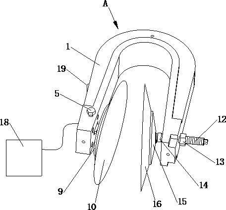
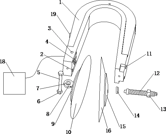
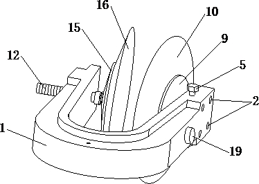
[0048] like Figure 1 to Figure 4 As shown, a vibration testing device for an aircraft airfoil structure of the present invention comprises a U-shaped piece 1, a left transmission mechanism and a right transmission mechanism respectively arranged on both sides of the U-shaped piece 1, and the U-shaped piece 1 A vibration exciter 18 that drives the U-shaped piece 1 to vibrate is provided on the upper side, and a dynamic force sensor 19 is provided on the left outer side of the U-shaped piece 1 .

[0049] The left transmission mechanism includes a pin 5 that is worn on the left side of the U-shaped piece 1 , an ear plate 8 that is sleeved on the pin 5 and extends out of the U-shaped piece 1 , and is connected to the ear plate 8 . The left conical piece 10 connected to and located on the inner side of the U-shaped piece 1, the ear plate 8 is embedded with a joint bearing 7 for the pin 5 to pass through.

[0050] The right transmission mechanism includes a threaded ejector rod 12...


PUM


Abstract

The invention discloses a vibration test device and a vibration simulation method for an aircraft airfoil structure, the device comprises a U-shaped piece, a left transmission mechanism and a right transmission mechanism which are respectively arranged on two sides of the U-shaped piece, a vibration exciter for driving the U-shaped piece to vibrate is arranged on the U-shaped piece, and a dynamic force sensor is arranged on the outer side of the left side of the U-shaped piece. The left transmission mechanism comprises a pin, a lug plate and a left conical part, the right transmission mechanism comprises a threaded ejector rod and a right conical part, the left conical part and the right conical part are clamped on the two sides of the airfoil structure respectively, and the device can achieve vibration transmission, can also clamp airfoil structures of different thicknesses and cannot cause abrasion to the skin surface of the airfoil structure. The method comprises the following steps: 1, installing a vibration testing device; 2, vibration simulation test is carried out on the airfoil structure, the vibration simulation test is carried out on the airfoil structure of the airplane, the accuracy of vibration simulation is high, and the effect is good.

Description

technical field [0001] The invention belongs to the technical field of vibration testing of aircraft airfoil structures, and in particular relates to a vibration testing device and a vibration simulation method for aircraft airfoil structures. Background technique [0002] Airfoils refer to various aerodynamic surfaces of aircraft, including wings, tails, rudder surfaces and ailerons, etc. For the vibration test of the aircraft airfoil structure, the vibration loading method is mainly to force the airfoil structure through the excitation rod. Vibration, the exciter rod needs to be connected and tightened with the airfoil structure during the specific operation. The conventional bolt connection requires prefabricated bolt holes on the airfoil structure, but the bolt holes will destroy the integrity of the airfoil structure, so there are many existing connection methods. Adhesion and connection with vacuum suction cups are adopted. [0003] On the one hand, although the bondi...

Claims


Application Information

Patent Timeline
Patent Type & Authority Applications(China)
IPC IPC(8): G01M7/02B64F5/60
CPCG01M7/025G01M7/027B64F5/60
Inventor 何石王彬文刘海涵王纯张飞黄文超
Owner CHINA AIRPLANT STRENGTH RES INST
Why Eureka
Try Eureka