Circularly polarized laser pen and laser remote interaction device

A circularly polarized light and laser pointer technology, which is applied in the field of laser remote interaction, can solve the problems of weak optical signal strength and inability to accurately obtain laser information, and achieve the effect of avoiding abnormal functions.

Inactive Publication Date: 2021-01-05
TCL CHINA STAR OPTOELECTRONICS TECH CO LTD
View PDF6 Cites 3 Cited by
  • Summary
  • Abstract
  • Description
  • Claims
  • Application Information

AI Technical Summary

Problems solved by technology

[0006] The embodiment of the present application provides a circularly polarized laser pointer and a laser remote interactive device, which are used to solve the problem that the laser emitted by the existing laser pointer is a kind of polarized light. If the interactive

Method used


Image

  • Circularly polarized laser pen and laser remote interaction device
  • Circularly polarized laser pen and laser remote interaction device
  • Circularly polarized laser pen and laser remote interaction device

Examples


Embodiment 1

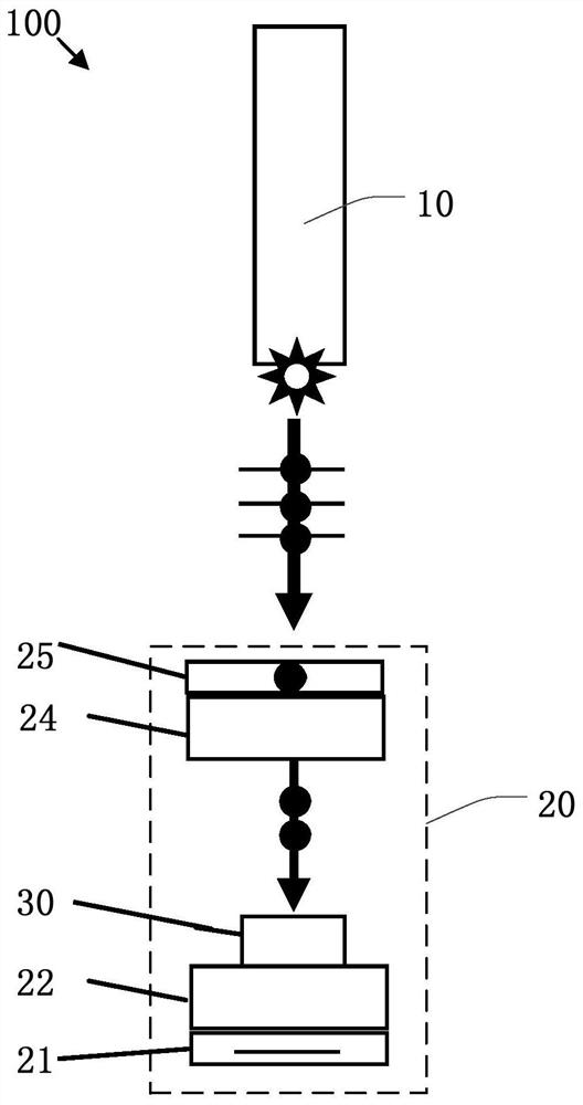
[0041] Such as figure 2 As shown, Embodiment 1 of the present application provides a laser remote interaction device 100 , which includes a circularly polarized laser pointer 10 and a display screen 20 .

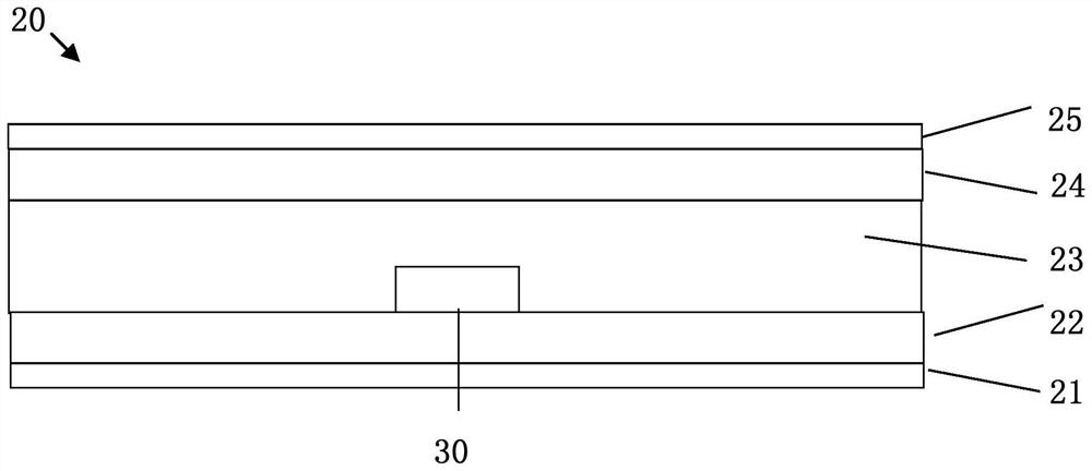
[0042] Such as image 3 As shown, in this embodiment, the display screen 20 is provided with a light sensor 30 for receiving the laser light emitted by the circularly polarized laser pointer 10 .

[0043] Such as image 3 As shown, in this embodiment, the display screen 20 further includes a lower polarizer 21, an array substrate 22, a liquid crystal layer 23, a color filter substrate 24, and an upper polarizer 25 that are sequentially stacked from bottom to top; specifically, the The array substrate 22 is set on the lower polarizer 21; the liquid crystal layer 23 is set on the array substrate 22; the color filter substrate 24 is set on the liquid crystal layer 23; the upper polarizer 25 is set on the color filter substrate 24 .

[0044] Such as image 3 As shown, in t...

Embodiment 2

[0058] Such as Figure 6 As shown, the embodiment 2 includes most of the technical features of the embodiment 1, the difference is that the first housing 2 and the second housing 8 in the embodiment 2 are integrally arranged instead of the embodiment 1 One end of the first shell 2 is sheathed on the outer surface of the second shell 8 .

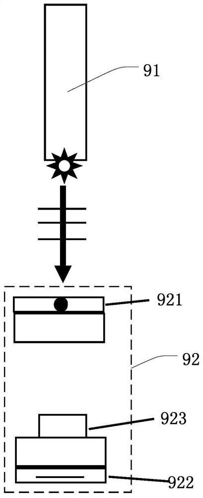
[0059] The principle of the laser remote interaction device 100 is the same as that of Embodiment 1, both as figure 2 As shown, the laser emission of the linearly polarized light emitting unit 11 is a circularly polarized laser (indicated by a solid arrow in the figure), and the circularly polarized laser is a circularly polarized light. When passing through the upper polarizer 25 of a display screen 20, no further Considering that the polarization direction of the laser is perpendicular to the polarization axis of the upper polarizer 25, the intensity of the laser passing through the upper polarizer 25 will not become weaker, thereby ensur...


PUM

PropertyMeasurementUnit
Angleaaaaaaaaaa

Abstract

The invention discloses a circularly polarized laser pen and a laser remote interaction device. The laser remote interaction device comprises a circular polarization laser pen and a display screen. The circular polarization laser pen comprises a linear polarization emission unit and a circular polarization conversion unit. The linear polarization emission unit is used for providing a linearly polarized light laser; and the circular polarization conversion unit is used for converting the linearly polarized light laser into a circular polarized light laser. The invention provides the special circularly polarized laser pen, and therefore, the problem that laser information cannot be accurately acquired due to the use angle of the laser pen is avoided, and functional abnormity caused by laserpolarization is avoided.

Description

technical field [0001] The present application relates to the technical field of laser remote interaction, in particular to a circularly polarized laser pointer and a laser remote interaction device. Background technique [0002] In the era of 5G and the Internet of Things, the Internet of Everything has become the future development trend. In addition to the basic functions of display, the liquid crystal display screen will also undertake more interactive functions. Laser remote interaction is an important means of interaction and has a certain prospect in the education demonstration market. [0003] The medium involved in the interaction is a laser pointer and a display screen with integrated light sensors. Firstly, the light sensor is integrated into the LCD screen, and the sensing component and the display component are combined into one. Secondly, the laser is emitted by the laser pointer and irradiated on the LCD screen, and the coordinates irradiated by the laser a...

Claims


Application Information

Patent Timeline
IPC IPC(8): G02B27/28G09B17/02G02F1/1333G06F3/0488
CPCG02B27/286G09B17/02G02F1/1333G06F3/0488
Inventor 郭力
Owner TCL CHINA STAR OPTOELECTRONICS TECH CO LTD
Why Eureka
Try Eureka