Building solar potential calculation method considering pilot sight and weather conditions

A technology of weather conditions and calculation methods, applied in calculation, 3D modeling, complex mathematical operations, etc., can solve problems such as affecting the pilot's line of sight, tight land use, etc., to achieve the effect of accurate building solar energy potential

Pending Publication Date: 2021-01-05
NANJING UNIV
View PDF0 Cites 4 Cited by
  • Summary
  • Abstract
  • Description
  • Claims
  • Application Information

AI Technical Summary

Problems solved by technology

However, the land on the Nansha islands and reefs is extremely tight, and the distance between the airstrip and the building area is

Method used


Image

  • Building solar potential calculation method considering pilot sight and weather conditions
  • Building solar potential calculation method considering pilot sight and weather conditions
  • Building solar potential calculation method considering pilot sight and weather conditions

Examples


Example Embodiment

[0045]The following describes the present invention in detail based on the drawings to make the technical route and operation steps of the present invention clearer.

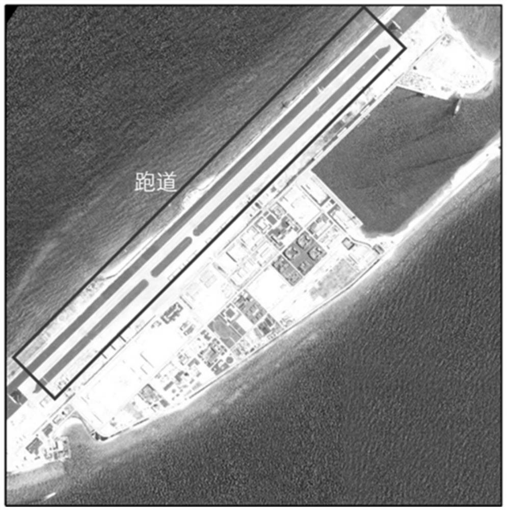
[0046]The embodiment of this technical solution is a region such asfigure 1 As shown, there are runways and surrounding buildings in the area, the runway is about 3 kilometers long, there are 147 buildings, and the building roof area is about 157,368m2, The elevation area is about 179 854m2, The buildings are mostly low-rise buildings. First calculate the solar energy potential of the building under standard atmospheric conditions, and then perform weather correction and visibility analysis.

[0047]This embodiment takes the experimental area as an example to illustrate a method for calculating the three-dimensional solar energy potential of a building, which specifically includes the following steps:

[0048]Step 1. Building model roof and facade point cloud sampling-based on the building LOD1 model, use CloudCompare software...


PUM


Abstract

The invention relates to a building solar potential calculation method considering pilot sight and weather conditions. The method comprises the steps of building model roof and facade point cloud sampling, building shielding analysis, sky vision field analysis, solar irradiance calculation, weather correction by utilizing measured data, intervisibility analysis according to pilot viewpoints, and statistics of solar potential of available areas under actual weather conditions. In the process of calculating the solar potential of a building, the influence of the actual weather condition is added, the influence of photovoltaic panels installed around the runway on the sight of a pilot is comprehensively considered, and a solar potential calculation result is closer to the actual condition.

Description

technical field [0001] The invention relates to a method for calculating the solar energy potential of a building considering the influence of weather conditions on sunlight and the influence of photovoltaic power generation panels on the pilot's line of sight. The steps of model, weather measurement data correction, and pilot's point-of-view analysis effectively estimate the solar power generation potential of buildings under actual weather conditions without affecting the pilot's sight. Background technique [0002] With the continuous development of the world economy, the extensive use of fossil energy has caused a series of serious environmental pollution problems. China has promised to reach the peak of carbon emissions before 2030 and increase the proportion of non-fossil energy to 20%. In 2017, China produced 6.49×10 3 TWh of electricity, however, 71.82% of it is generated by coal, and only 1.49% is generated by solar energy. Therefore, estimating the potential of s...

Claims


Application Information

Patent Timeline
IPC IPC(8): G06F30/13G06T17/00G06F17/11
CPCG06F17/11G06T17/00G06F30/13
Inventor 程亮李舒怡谌颂阮晓光庄启智陈辉姚云长顾一帆刘磊楚森森
Owner NANJING UNIV
Why Eureka
Try Eureka