High-temperature electric tracing band

A technology of electric heating cable and high temperature, which is applied in the direction of ohmic resistance heating parts, heating elements, heating element shape, etc., which can solve problems such as damage, waste of time, and affect the normal use of electric heating cable, so as to ensure normal use and avoid damage Effect

Active Publication Date: 2021-01-05
ANBANG ELECTRICAL GRP
View PDF26 Cites 0 Cited by
  • Summary
  • Abstract
  • Description
  • Claims
  • Application Information

AI Technical Summary

Problems solved by technology

[0002] There are many benefits of electric heating cables. Electric heating cables are easy to carry and easy to operate. Electric heating cables are also very safe and will not cause harm to people. The application range of electric heating cables is very wide. It can be used for heating pipelines , can avoid the temperature is too low in winter, the condensation of water in the pipeline, to ensure the normal delivery of water, but also can melt the snow on the roof, ground or some necessary places in winter, to avoid the generation of snow, to ensure the smoothness of the road , when the traditional heating cable melts snow on a large area of ​​snow, the contact area with the snow is small, it cannot melt the snow quickly, the work efficiency is low, and the capacity wastes a lot of time. The traditional electric heating cable needs Only when the metal contact head is energized can the heat be released. The traditional metal contact head is relatively fragile, and it is easy to cause damage when it is exposed to the air for a long time when not in use, thus affecting the normal use of the electric heating cable.

Method used


Image

  • High-temperature electric tracing band
  • High-temperature electric tracing band
  • High-temperature electric tracing band

Examples


Embodiment 1

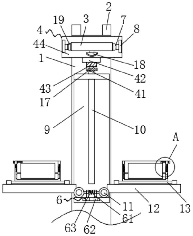
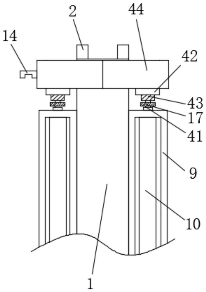
[0026] Such as Figure 1-3 As shown, the present invention provides a high-temperature electric heating cable, including an electric heating cable body 1, one end of the electric heating cable body 1 is provided with a metal contact 2, and the front and back of the electric heating cable body 1 are fixedly connected with installation Shell 9, the left and right sides of the installation shell 9 are provided with first through holes, the upper surface of the installation shell 9 is clamped with the protection mechanism 4, and the lower surface of the inner wall of the installation shell 9 is clamped with two fourth bearings, the fourth bearing The inner sleeve is provided with a fourth rotating shaft 11, the outer surface of the fourth rotating shaft 11 is fixedly connected to the limiting plate 12, the upper surface of the limiting plate 12 is clamped with two fifth bearings, and the inner sleeve of the fifth bearing is provided with a fifth rotating shaft 13 , the upper surfa...

Embodiment 2

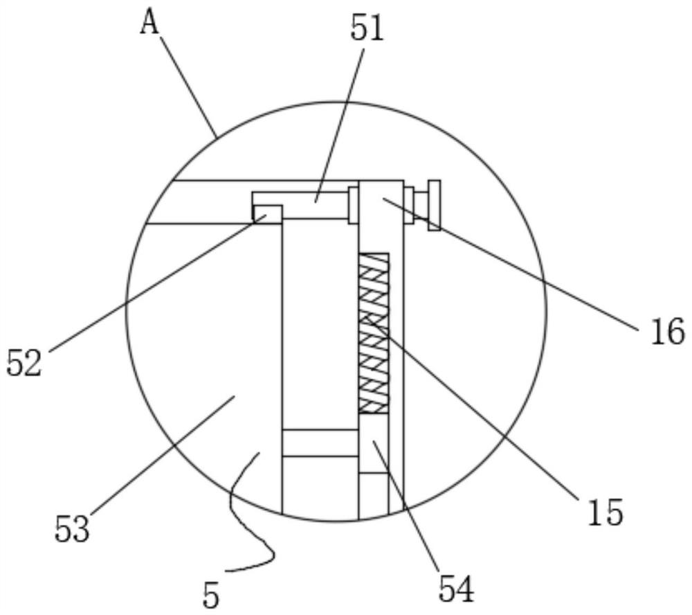
[0029] This embodiment provides a high-temperature electric heating cable, which differs from Embodiment 1 in that, as image 3 As shown, the extension mechanism 5 includes a second rotating shaft 51, a stopper 52 and an extension plate 53. The left and right sides of the inner wall of the heat conduction cover 16 are provided with a first chute, and the first chute is slidably connected with a first chute. Block 54, one side of the first sliding block 54 is fixedly connected with an extension plate 53 through an extension rod, the upper surface of the extension plate 53 fits with the block 52, and the block 52 is fixedly connected with the outer surface of the second rotating shaft 51, the second The rotating shaft 51 is sheathed in the second bearing that is clamped on one side of the heat conduction cover 16 , and one end of the second rotating shaft 51 is fixedly connected with a handle.

[0030] In practical applications, when it is necessary to further increase the snowm...

Embodiment 3

[0032] This embodiment provides a high-temperature electric heating cable, which differs from Embodiment 2 in that, as Figure 1-3 As shown, the limit mechanism 6 includes an insertion rod 61 and a first spring 63, two insertion rods 61 are arranged on the lower surface of the inner wall of the installation shell 9, and the other end of the insertion rod 61 is inserted on a side of the fourth rotating shaft 11 and opened. In the limit groove of the slit, the front of the insertion rod 61 is fixedly connected with a pressure rod, and the pressure rod passes through the second through hole opened on the front of the installation shell 9 and extends to the outside of the installation shell 9, and the two insertion rods 61 are fixed by the first spring 63 connect.

[0033] In practical applications, when it is necessary to initially increase the snow melting area, move the two pressure blocks closer to the middle and squeeze the first spring 63, so that the insertion rod 61 moves ...


PUM


Abstract

The invention discloses a high-temperature electric tracing band, and relates to the technical field of electric tracing bands. The electric tracing band comprises an electric tracing band body, wherein a metal contact is arranged at one end of the electric tracing band body, mounting shells are fixedly connected to the front surface and the back surface of the electric tracing band body, and first through holes are formed in the left side surface and the right side surface of each mounting shell. According to the scheme, the two mounting shells are arranged, the mounting shells and the electric tracing band body are buried in snow, the front-back contact area of the electric tracing band body can be increased through the two mounting shells, and therefore the snow melting capacity is preliminarily improved; by arranging a limiting plate and a heat conduction cover, the left-right contact area of the electric tracing band body is increased; through the arrangement of an extending mechanism, the rotation of the second rotating shaft can relieve the limitation of the baffle block on the extension plate, so that the extension plate extends out of the heat conduction cover under the action of the elastic force of the second spring, the contact area between the electric tracing band body and snow is increased again, the snow melting efficiency of the electric tracing band body is improved, and a large amount of time is saved.

Description

technical field [0001] The invention relates to the field of electric heating cables, in particular to a high-temperature electric heating cable. Background technique [0002] There are many benefits of electric heating cables. Electric heating cables are easy to carry and easy to operate. Electric heating cables are also very safe and will not cause harm to people. The application range of electric heating cables is very wide. It can be used for heating pipelines , can avoid the temperature is too low in winter, the condensation of water in the pipeline, to ensure the normal delivery of water, but also can melt the snow on the roof, ground or some necessary places in winter, to avoid the generation of snow, to ensure the smoothness of the road , when the traditional heating cable melts snow on a large area of ​​snow, the contact area with the snow is small, it cannot melt the snow quickly, the work efficiency is low, and the capacity wastes a lot of time. The traditional el...

Claims


Application Information

Patent Timeline
Patent Type & Authority Applications(China)
IPC IPC(8): H05B3/06H05B3/56
CPCH05B3/06H05B3/56
Inventor 李贻连卜基峰姚月凤
Owner ANBANG ELECTRICAL GRP
Why Eureka
Try Eureka