Tool and method for quickly adjusting equipment before thread rolling

A technology of rapid adjustment and adjustment method, which is applied in the direction of threaded products, other household appliances, household appliances, etc., can solve the problems of unfavorable production organization, low adjustment accuracy, time-consuming and labor-intensive, etc., and achieve simplified axial relative position Effect of adjustment process, simplified adjustment process, and convenient measurement

Inactive Publication Date: 2021-01-08
YICHANG MARINE DIESEL ENGINE
View PDF7 Cites 0 Cited by
  • Summary
  • Abstract
  • Description
  • Claims
  • Application Information

AI Technical Summary

Problems solved by technology

It is time-consuming and labor-intensive to adjust during thread rolling, and it depends entirely on the experience of the operator. The adjustment accuracy is low and the efficiency is low, which is not conducive to production organization.

Method used


Image

  • Tool and method for quickly adjusting equipment before thread rolling
  • Tool and method for quickly adjusting equipment before thread rolling
  • Tool and method for quickly adjusting equipment before thread rolling

Examples


Embodiment 2

[0050] The method for adjusting the quick adjustment tooling of the equipment before thread rolling and rolling comprises the following steps:

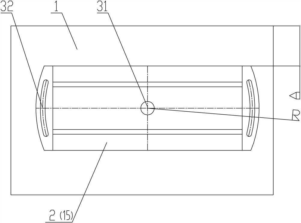
[0051] Step 1, the rotation angle adjustment of the first rotating base 2 and the second rotating base 15, that is, the adjustment of the helix angle:

[0052] According to the helix angle λ of the rolled thread, the value of the rotation angle of the first rotating base 2 is converted into the vertical distance A between the outer edge of the top of the first rotating base 2 and the top of the bed 1;

[0053] The rotation angle value of the second rotating base 15 is converted into the vertical distance A between the top outer edge of the second rotating base 15 and the top of the driving cylinder block 16;

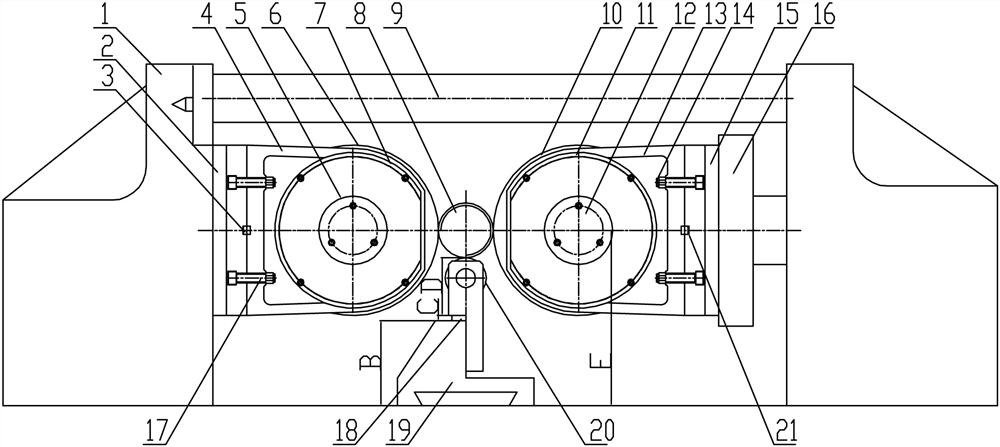
[0054] Step 2, the height adjustment of the lower support roller 20:

[0055] The outer circle of the finished workpiece, the height B of the roller seat 19, the height D of the support roller 20 and the height F of the spindle...

Embodiment 3

[0072] 1. Helix angle adjustment: By first measuring the distance between the bases on both sides and the bed when the angle of the main shaft of the equipment is zero degrees, and using this value as a reference to add or subtract the rotation amount of the rotating base, the inclination of the two main shafts can be accurately adjusted The angle corresponds to the helix angle of the rolled thread. For specific values, see Figure 4 . In this embodiment, the R is 330mm.

[0073] 2. Height adjustment pad thickness adjustment: by the attached figure 2 It can be obtained that the thickness of the spacer = the height of the center of the main shaft - the height of the roller seat - the height of the roller. For this reason, the thickness of the spacers for all the threaded threads is calculated, and the corresponding spacers are prepared in advance. When adjusting, select the corresponding spacers according to the size of the table That's it. For specific values, see Figur...


PUM


Abstract

The invention provides a tool and method for quickly adjusting equipment before thread rolling. A first rotating base is mounted on one inner side wall of a lathe bed, and a first bearing seat is located and mounted on the side wall of the first rotating base; a first thread rolling cylindrical die is mounted on the first bearing seat; a driving cylinder seat is installed on the other inner side wall of the lathe bed, and a second rotating base is installed on the driving cylinder seat; a second bearing seat is located and installed on the side wall of the second rotating base, and a second thread rolling cylindrical die is installed on the second bearing seat, and cooperatively connected with a rotating cylinder used for driving the second thread rolling cylindrical die to rotate; a supporting roller is arranged at the bottom of the lathe bed and located below the position between the first thread rolling cylindrical die and the second thread rolling cylindrical die; and the supporting roller is supported on the top of a roller seat through a roller bracket and a height adjusting cushion block.

Description

technical field [0001] The invention belongs to the technical field of screw thread rolling processing, and in particular relates to a quick adjustment tool and method for equipment before thread rolling and rolling. Background technique [0002] Ordinary thread rolling machine needs to adjust the axial synchronization of the paired thread rolling wheels before thread rolling, that is, the axial tooth surface needs to be accurately adjusted to a difference of half a pitch, and at the same time, the inclination angle of the two spindles and the processed thread must be accurately adjusted. The helix angle is consistent and the center of the workpiece on the lower support roller is the same as the height of the spindle center or 0.1-0.2mm lower. Since the equipment does not have precise angle adjustment facilities, there is only an angle scale with a graduation accuracy of 0.5 degrees; the axial adjustment is adjusted by threaded adjustment spacers, and there is no way to make...

Claims


Application Information

Patent Timeline
Patent Type & Authority Applications(China)
IPC IPC(8): B21H3/04
CPCB21H3/042
Inventor 朱中敏邱国良张科
Owner YICHANG MARINE DIESEL ENGINE
Why Eureka
Try Eureka