Welding equipment convenient to use
A kind of welding equipment and convenient technology, which is applied in welding equipment, auxiliary welding equipment, welding/cutting auxiliary equipment, etc., can solve the problems that the welding body and joints cannot be fixed, fall off, and affect normal work, so as to avoid poor contact and electric current Sexual connection is stable and the effect of increasing the contact area
- Summary
- Abstract
- Description
- Claims
- Application Information
AI Technical Summary
Problems solved by technology
Method used
Image

Examples
Embodiment 1
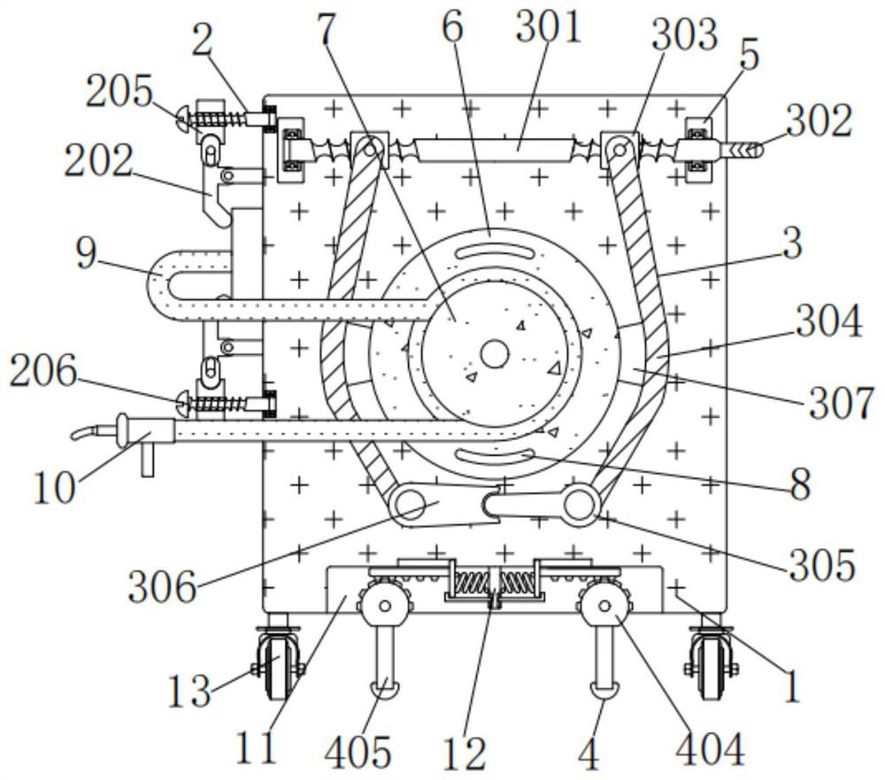
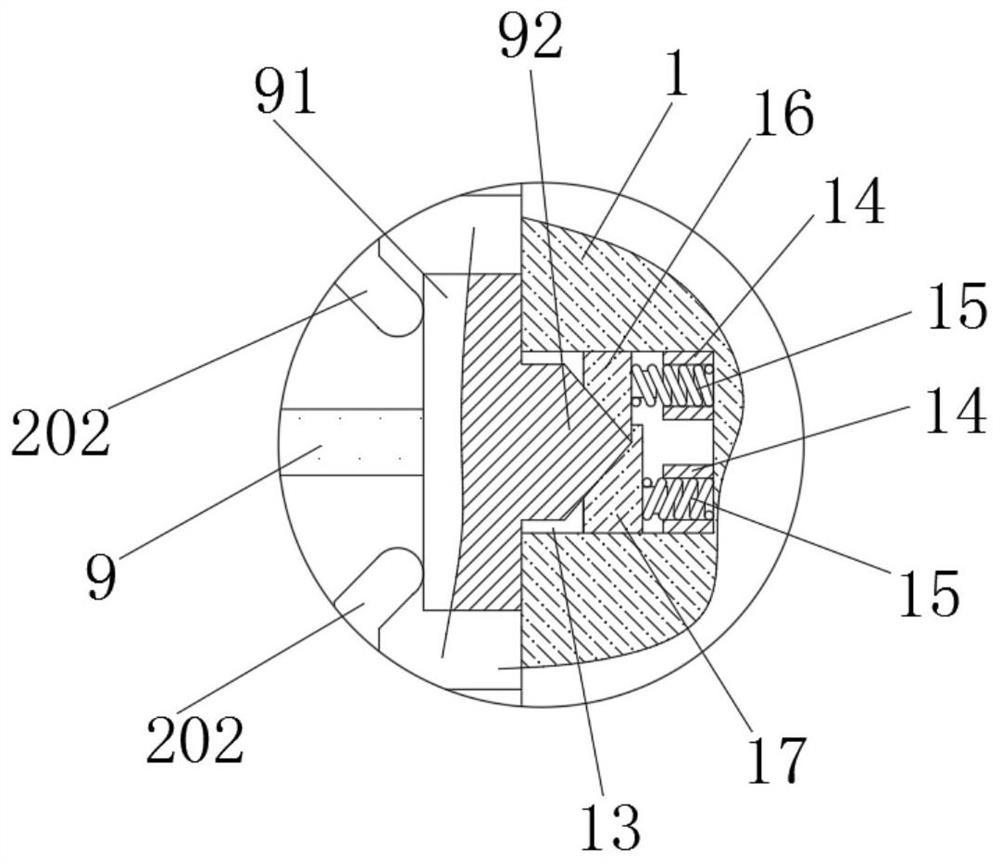
[0035] A kind of welding equipment, including a welding body 1, the model of the welding body 1 is ZX7-400, the left side of the welding body 1 is electrically connected with a connecting line 9 through a contact body 91, and the connection line 9 between the contact body 91 and the connecting line 9 The ground wire is electrically connected, the connecting wire 9 is powered by the welding body 1, the contact body (91) is pressed on the welding body by a fixing mechanism, and the left side of the welding body (1) above and below the contact body (91) is installed There is a fixing mechanism (2); the right side of the contact body (91) is provided with a triangular rib (92), the left side of the welding body (1) is provided with a contact groove (13), and the bottom of the contact groove (13) is provided with Two spring installation grooves (14) distributed up and down, the upper spring installation groove (14) is installed with the upper contact piece (15) through the conductio...
Embodiment 2
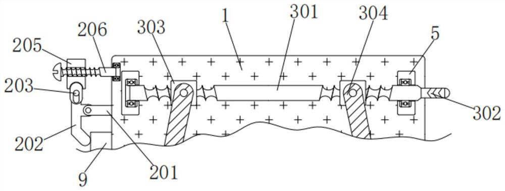
[0038] As an option, see figure 1 , 3 and 5, used for welding equipment, the front of the welding body 1 is rotatably connected with a disc 6, the disc 6 is forced to rotate through the front pin shaft of the welding body 1, the front of the disc 6 is fixedly connected with a sheave 7, and the connecting wire The outer wall of 9 is wound and connected with the outer wall of the sheave 7. When the disc 6 rotates to drive the sheave 7, the connecting wire is wound or spread out to both sides at the same time. A welding torch 10 is connected to the left side below the outer wall of the connecting wire 9. The material of the welding torch 10 is 18AK , the upper and lower sides of the front of the disc 6 are fixedly connected with handles 8, the handles 8 are convenient to rotate the disc 6, and the upper and lower sides of the front of the welding body 1 are fixedly connected with vertical plates 5, and the inner walls of the two vertical plates 5 are equipped with Regulating mecha...
Embodiment 3
[0041] As an option, see figure 1 , 6 and 7, for welding equipment, the left and right sides of the vertical plate 12 are equipped with a limit mechanism 4, the limit mechanism 4 includes a spring 401, a thin plate 402, a rack 403, a gear 404, a thick rod 405, a rubber sleeve 406 and a curved plate 407, the inner sides of the two springs 401 are respectively affixed to the left and right sides of the riser 12, and the outer sides of the two springs 401 are respectively affixed to the inner sides of the thin plate 402, and the thin plate 402 rebounds through the spring 401 after being moved under force, The tops of the two thin plates 402 are slidingly engaged with the left and right sides of the inner wall top of the groove 11 respectively, the thin plates 402 slide left and right through the inner wall top of the groove 11 under force, and the outer sides of the two thin plates 402 are fixedly connected with the inner sides of the rack 403 respectively , the bottoms of the t...
PUM
 Abstract
Description
Claims
Application Information
 - R&D
- Intellectual Property
- Life Sciences
- Materials
- Tech Scout
- Unparalleled Data Quality
- Higher Quality Content
- 60% Fewer Hallucinations
Browse by: Latest US Patents, China's latest patents, Technical Efficacy Thesaurus, Application Domain, Technology Topic, Popular Technical Reports.
© 2025 PatSnap. All rights reserved.Legal|Privacy policy|Modern Slavery Act Transparency Statement|Sitemap|About US| Contact US: help@patsnap.com