Auxiliary air inlet device for internal ventilation of power distribution cabinet

A technology of air intake device and power distribution cabinet, which is applied in the direction of cooling/ventilation of substation/distribution device casing, pump device, substation/switchgear, etc. , local wind speed and other problems, to avoid gaps or air inlets easily entering dust, maintain the same air pressure inside and outside the box, and reduce airflow intensity

Active Publication Date: 2020-09-29
重庆华美电力设备有限责任公司
View PDF17 Cites 0 Cited by
  • Summary
  • Abstract
  • Description
  • Claims
  • Application Information

AI Technical Summary

Problems solved by technology

[0005] The purpose of the present invention is to provide an auxiliary air intake device for ventilation inside the power distribution cabinet to solve the problem that the cooling fans of the existing power distribution cabinet proposed in the above-mentioned background technology are generally arranged in a centralized manner, which will cause relatively large local wind speeds and relatively large wind speeds. Atmospheric airflow will cause the circuit and the contact part of the electrical appliance to ignite, and the general cooling fan is generally set in the way of exhaust, which will cause the air pressure in the power distribution cabinet to be lower than the external air pressure during work, and the external air will be Entering through the gaps and air inlets, it is easy to bring in the problem of dust

Method used


Image

  • Auxiliary air inlet device for internal ventilation of power distribution cabinet
  • Auxiliary air inlet device for internal ventilation of power distribution cabinet
  • Auxiliary air inlet device for internal ventilation of power distribution cabinet

Examples


Embodiment Construction

[0028] The following will clearly and completely describe the technical solutions in the embodiments of the present invention with reference to the accompanying drawings in the embodiments of the present invention. Obviously, the described embodiments are only some, not all, embodiments of the present invention.

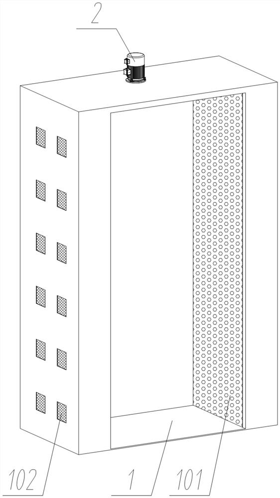
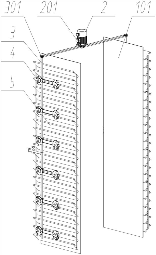
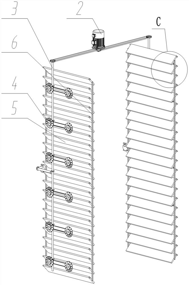
[0029] see Figure 1 to Figure 8, an embodiment provided by the present invention: an auxiliary air intake device for ventilation inside a power distribution cabinet, including an outer shell 1; a group of driving motors 2 are fixedly connected to the top of the outer shell 1; the driving motor 2 also includes Drive pulley 201, a group of drive pulleys 201 are coaxially fixedly connected to the rotating shaft of the driving motor 2, and the drive shaft 3 also includes a rotating shaft transmission pulley 301, and a group of rotating shaft transmission pulleys 301 is fixedly connected to the top of the driving shaft 3. A group of synchronous transmission belts are wou...


PUM


Abstract

The invention discloses an auxiliary air inlet device for internal air exchange of a power distribution cabinet, relates to the technical field of power distribution cabinets, and solves problems thata cooling fan of an existing power distribution cabinet is relatively high in local wind speed, relatively large air flow can cause line sparking at a contact part of a line and an electric appliance, and external air enters from a gap and an air inlet, and dust is easily brought in. The device comprises an outer shell, wherein the top of the outer shell is fixedly connected with a group of driving motors, the interiors of a left side wall and a right side wall of the outer shell are each rotationally connected with a set of driving shafts, the left inner side and the right inner side of theouter shell are each rotationally connected with multiple sets of air deflectors, inner sides of left and right rear portions of the outer shell are each rotationally connected with a set of air guidedriving shafts. The device is advantaged in that the device effectively avoids the problem of line sparking caused by large airflow at the contact part of the line and the electric appliance, maintains consistency of internal and external air pressures of a box body, and effectively avoids the problem that dust easily enters gaps or air inlets due to low internal air pressure of the power distribution cabinet.

Description

technical field [0001] The invention relates to the technical field of power distribution cabinets, in particular to an auxiliary air intake device for ventilation inside the power distribution cabinet. Background technique [0002] Power distribution cabinets are often used in electrical engineering. Electrical components will generate heat during work. If the electrical components are overheated, electrical components will burn out. In order to cool down the electrical components, a cooling fan is generally installed on the power distribution cabinet to increase the temperature of the electrical components. Cooling speed. [0003] For example, application number: CN201610505485.9 The present invention discloses a power distribution cabinet, which includes a cabinet body with an opening at the front end, and a cabinet door connected to the front end of the cabinet body through hinges; Low slope board; the lower part of the rear cabinet in the cabinet is located above the m...

Claims


Application Information

Patent Timeline
Patent Type & Authority Applications(China)
IPC IPC(8): H02B1/30H02B1/56H02B1/28F04D25/08F04D25/16
CPCH02B1/30H02B1/565H02B1/28F04D25/08F04D25/166
Inventor 陈飞华
Owner 重庆华美电力设备有限责任公司
Why Eureka
Try Eureka