Apparatus and method for regulation of fluid flow from a straw

Inactive Publication Date: 2008-01-31
BYERLY JENNIFER
View PDF19 Cites 10 Cited by
  • Summary
  • Abstract
  • Description
  • Claims
  • Application Information

AI Technical Summary

Benefits of technology

[0021]When calculated properly for distance between the top and bottom walls, density and size of the ball, and the anticipated acceleration of the fluid though the chamber between the two apertures, the ball will only seat when the fluid flow reaches sufficient velocity to force it the distance to the seat. Once seated, fluid flow will cease, causing the ball to drop away from the seat due to a higher density than the fluid. In this fashion, the velocity of the fluid stream exiting the straw can be limited not to exceed a certain speed, thereby providing a means to prevent a user from sucking too hard and having fluid accidentally traverse the throat into the lungs from slow reflexes. Further, the total potential volume allowed per suck on the straw may be reasonably accurately determined by forming the ball of a size and material yielding a density to seat the ball against the spaced top wall and seat, only after a determined period of time, depending on the strength of the user sucking on the straw and accelerating the fluid stream. A hard and quick suck will yield quicker fluid acceleration and a faster sealing of the flow since the ball will be forced up quickly to cease flow. A softer sucking action will yield a slower fluid flow and a longer time for the ball to rise to the seat if the specific gravity of the ball and its exterior dimensions are correctly calculated to cause it to rise in the direction of the fluid stream with minimal fluid acceleration. Further adjustments for volume allowed in any one sucking of the straw may be provided by spacing distance of the top wall from the bottom wall and thus the total volume of the chamber and total distance the ball must travel to seat and cease flow.
[0022]As such, the device may be positioned inside of disposable drinking straws during manufacuture, and based on the calculations above for specific gravity, fluid acceleration, and exterior dimensions of the ball causing lift, different flow rates and maximum amounts of fluid may be provided by different straws. The differing straws may be provided with some type of indicia or colorization labeling

Problems solved by technology

Such patients may suffer from stroke causing facial paralysis to one side of the mouth or other motor function problems inhibiting muscular control of the mouth and throat.
For patients suffering from facial paralysis affecting one side of their mouths, or lack of muscle control, or lack of experience using a straw, there is an inherent risk if they are allowed to ingest the total volume of liquid reaching the distal end of the straw on which they are sucking.
Due to such poor control of the pharyngeal muscles, such patients may tend to draw too much fluid through a straw or be too slow to swallow the volume of fluid drawn therethrough and accelerated into the mouth and throat.
As a result of such inherent or acquired disabilities, many patients are in constant danger of ingesting too much fluid when sucking on a straw to drink or being unable to swallow effectively the volume of fluid naturally drawn into their mouths.
Either occurrence can result in the patient losing the drawn fluid out of their mouth or nose through choking or coughing, thereby yielding an emba

Method used


Image

  • Apparatus and method for regulation of fluid flow from a straw
  • Apparatus and method for regulation of fluid flow from a straw
  • Apparatus and method for regulation of fluid flow from a straw

Examples


Example

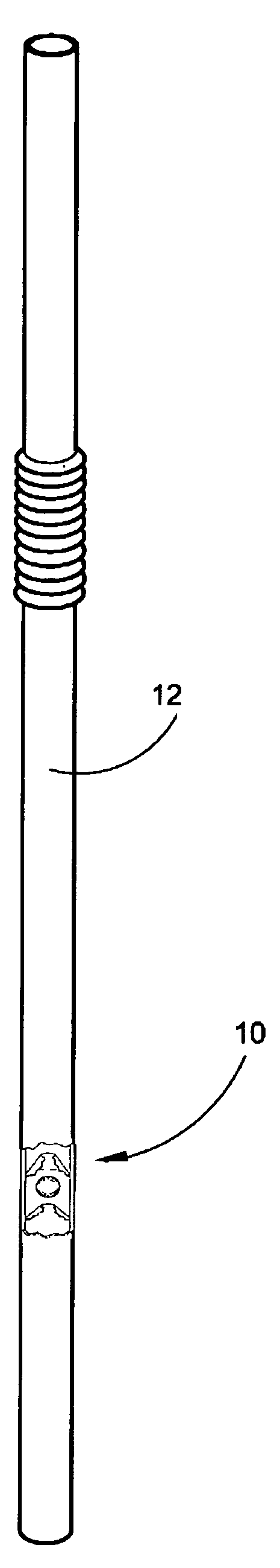
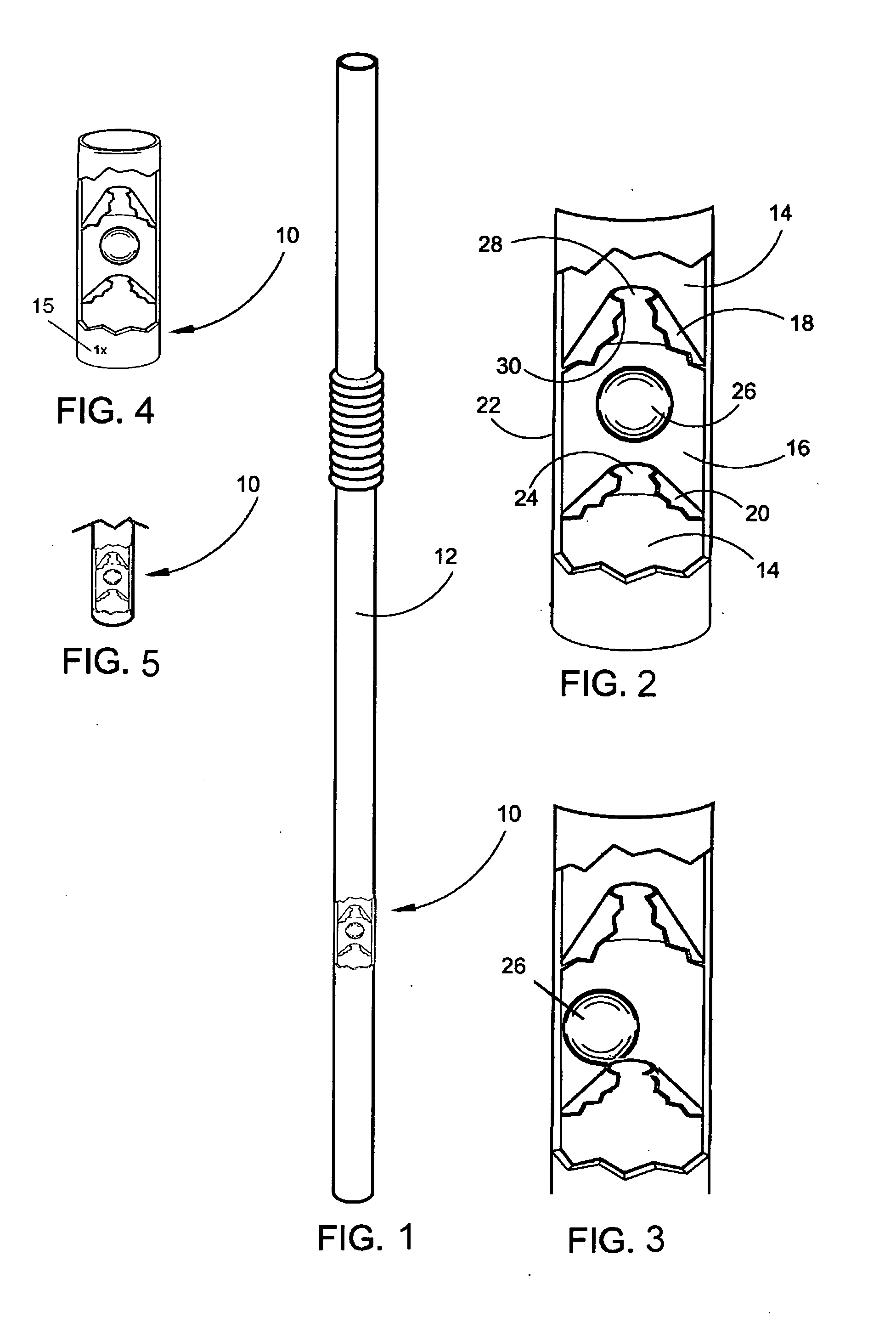
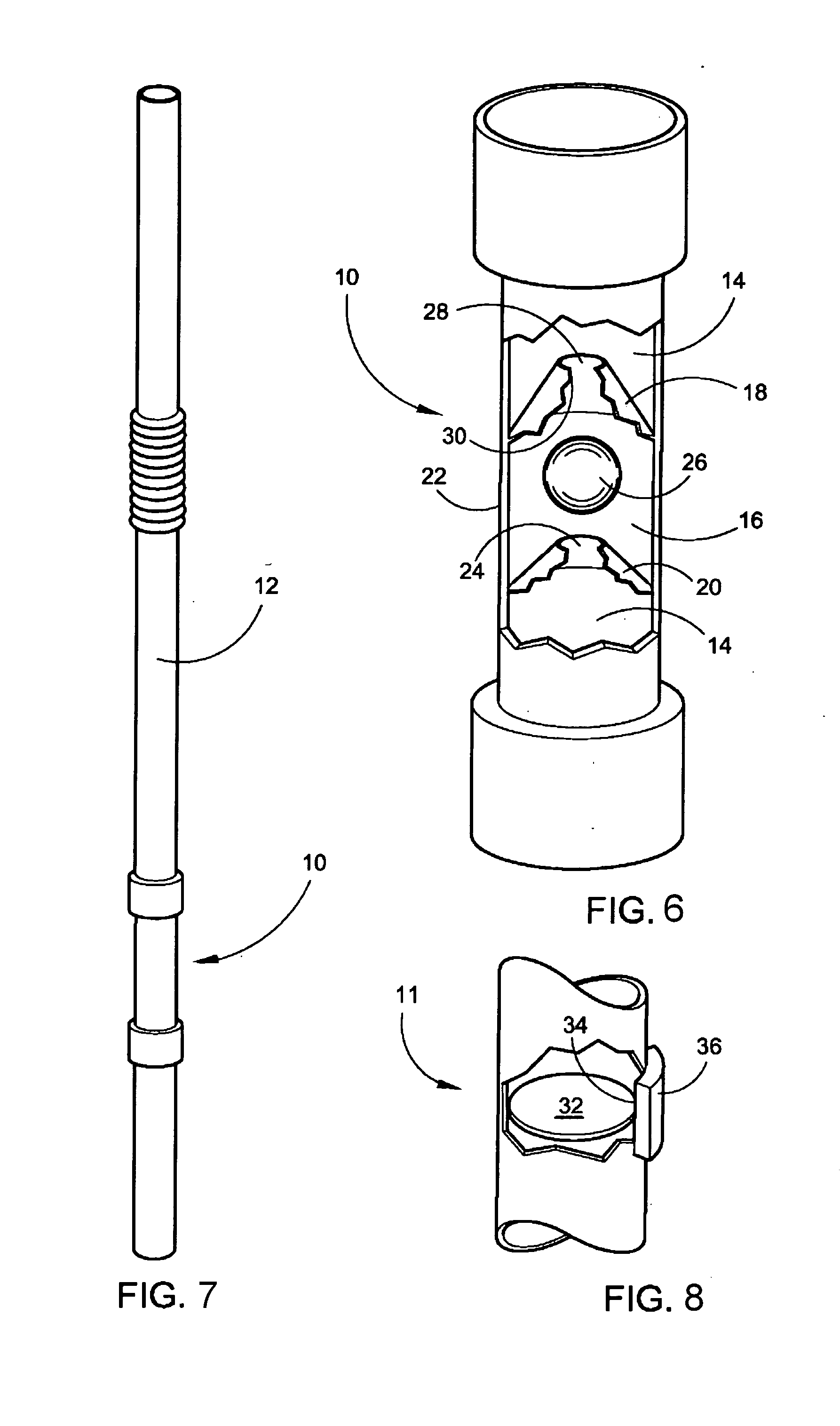
[0038]Referring now to the drawings, FIGS. 1-7 disclose modes of the device herein described and disclosed for regulating fluid velocity and volume when exiting a straw to a user's mouth.

[0039]In one preferred mode of the device 10 depicted in FIG. 1, with the device 10 disposed in a straw 12 during extrusion of the straw 12, an inexpensive and disposable means to regulate fluid velocity and maximum volume exiting a straw 12 is depicted. Because it is inexpensive to manufacture and install within the straw 12 during extrusion, the device 10 and straw 12 may be disposed once used and replaced to mitigate hygiene and sterility problems that occur with permanent devices for this purpose that collect food and germs thereon.

[0040]The straw 12 in all modes in which the device 10 is employed, has an axial passage 14 communicating therethrough in a conventional fashion from a lower end of the straw to the distal end, which would be engaged by the user's mouth. The device provides a restrict...


PUM


Abstract

A regulating component to regulate fluid flow through the axial passage communicating between the intake end, and mouth engageable distal end, of a drinking straw. The component has an upper wall separated from a lower wall by an engaged sidewall all defining a restriction chamber. When engaged in the axial passage of a drinking straw, fluid traversing the straw all traverses through apertures in the lower and upper wall and thereby through the restriction chamber. Force of the moving fluid on a ball in the restriction chamber acts to raise the ball to seal the aperture in the upper wall. If the fluid reaches too high a speed or continues long enough at a lower speed to move the ball upward it seals the restriction chamber from the exit end of the straw.

Description

FIELD OF THE INVENTION[0001]This application claims the benefit of U.S. Provisional Patent Application No. 60 / 830,493, filed Jul. 12, 2006. The disclosed device relates generally to a drinking straw. More particularly, the device relates to a straw for consumption of liquids which provides a regulated fluid flow of fluid volume and velocity from the distal end of the straw upon which suction is imparted by a user. The device is particularly useful for users having impaired control of mouth suction such as hospital and ambulatory patients or children who inherently tend to drink too fast and too much which can be dangerous to their health.BACKGROUND OF THE INVENTION[0002]Hospital and ambulatory patients frequently need to drink using a straw. While some such patients are able to employ a cup or limited pouring glass device, for many patients a straw is the only means for ingesting liquid from a container. Such patients may suffer from stroke causing facial paralysis to one side of th...

Claims


Application Information

Patent Timeline
IPC IPC(8): A47G21/18
CPCA47G21/18Y10T137/791
Inventor BYERLY, JENNIFER
Owner BYERLY JENNIFER
Why Eureka
Try Eureka