
A beam guide installation device for a steel structure gravel workshop

A technology for installing equipment and steel structures, which is applied in building construction, building material processing, construction, etc., and can solve problems such as changing the preset position of the support frame, collision between the beam and the inner and outer walls of the support frame, and low accuracy.

Active Publication Date: 2021-07-06
宜昌江山建设工程有限公司
View PDF8 Cites 0 Cited by
  • Summary
  • Abstract
  • Description
  • Claims
  • Application Information

AI Technical Summary

Problems solved by technology

[0005] The present invention can solve the problem of the installation equipment for beams used in traditional steel structure gravel workshops. When the beam support frame on the ground is pre-installed, the support frame will often have an inclination angle with the ground, resulting in an unstable angular position between the beam and the support frame in the later stage. , prone to inclination, and it is not convenient for positioning and installation, and the traditional steel structure gravel workshop uses beam installation equipment, which requires a large hoisting combination machine, the installation accuracy is low, and after the beam contacts the support frame, It is necessary to move the position of the beam by hoisting machinery. During this process, the inner and outer walls of the beam and the support frame are likely to collide, which will damage the inner and outer surfaces of the beam and the support frame, and it is easy to collide with the support frame, which will change the preset position of the support frame, which is not conducive to Difficulties such as the stability of the overall mechanism after installation

Method used


Image

  • A beam guide installation device for a steel structure gravel workshop
  • A beam guide installation device for a steel structure gravel workshop
  • A beam guide installation device for a steel structure gravel workshop

Examples


Embodiment Construction

[0029] The embodiments of the present invention will be described in detail below with reference to the accompanying drawings, but the present invention can be implemented in many different ways defined and covered by the claims.

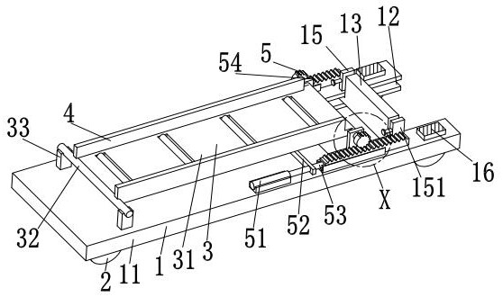
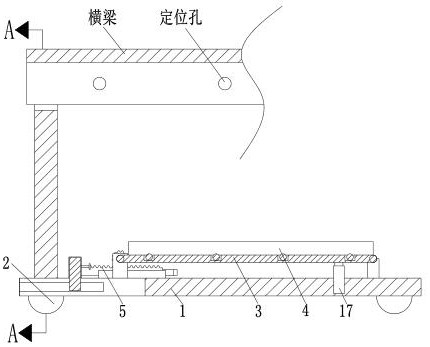
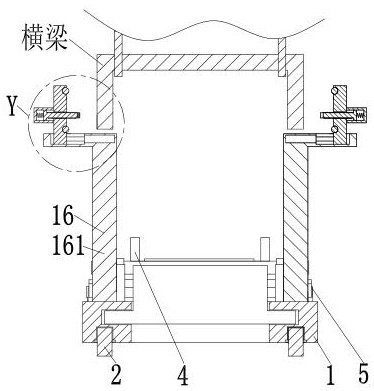
[0030] Such as Figure 1 to Figure 6 As shown, a beam guide installation equipment for a steel structure gravel factory building, including a mobile base 1, a roller 2, an overturning bottom plate 3, a baffle plate 4 and an overturning device 5, the lower end of the mobile base 1 is close to the four corners. Roller 2 is evenly installed in the way of rotation fit, and the top of the mobile base 1 is provided with an overturning base plate 3, and the front and rear sides of the upper end of the overturning base plate 3 are symmetrically fixed with baffles 4, and the right side of the overturning base plate 3 is provided with an overturning device 5, and the overturning Device 5 is installed on the upper right side of mobile base 1 .

[0031] The mo...


PUM


Abstract

The invention relates to a crossbeam guide installation device for a steel structure gravel factory building, which includes a moving base, rollers, an overturning bottom plate, a baffle plate and an overturning device, and the lower end of the moving base is evenly installed near the four corners by rotating There are rollers, the top of the mobile base is provided with an overturning base plate, the front and rear sides of the upper end of the overturning base plate are symmetrically fixed with baffle plates, the right side of the overturning base plate is provided with an overturning device, and the overturning device is installed on the upper right side of the mobile base. The invention can solve the problem of the installation of beams used in traditional steel structure gravel workshops. When the beam support frame on the ground is pre-installed, the support frame tends to have an inclination angle with the ground, which is prone to inclination and requires a large hoisting Combined machinery is not easy to install. When the hoisting machine moves the position of the beam, the beam is likely to collide with the inner and outer walls of the support frame, and damage the inner and outer surfaces of the beam and the support frame.

Description

technical field [0001] The invention relates to the technical field of construction of sand and gravel workshops, in particular to a crossbeam guiding installation device for steel structure sand and gravel workshops. Background technique [0002] A beam is a component of a building or frame, and refers to a transverse beam, that is, a beam perpendicular to the longitudinal beam, arranged along the short axis of the building. At present, when installing a large beam, it is usually necessary to pre-install the supporting end of the beam on the ground first, then lift the beam in the air, move the beam slowly, and position the beam between the beam and the support frame. Then manually or mechanically fix the position between the beam and the support frame, and then slowly remove the guide rails, racks, connecting plates, etc. at the joint of the beam to complete the positioning. [0003] At present, there are usually the following defects when guiding the installation of beam...

Claims


Application Information

Patent Timeline
Patent Type & Authority Patents(China)
IPC IPC(8): E04G21/16
CPCE04G21/16E04G21/162
Inventor 叶青海郑芹芹严小青
Owner 宜昌江山建设工程有限公司
Learn More