Lateral light-emitting optical fiber and backlight module with same

A backlight module and side-emitting technology, which is applied in optics, nonlinear optics, instruments, etc., can solve the problem of single light output mode of optical fiber, and achieve the effects of reducing loss, strong applicability of the overall structure, energy saving and environmental protection, and luminous brightness

Inactive Publication Date: 2021-01-08
深圳康佳电子科技有限公司
View PDF7 Cites 0 Cited by
  • Summary
  • Abstract
  • Description
  • Claims
  • Application Information

AI Technical Summary

Problems solved by technology

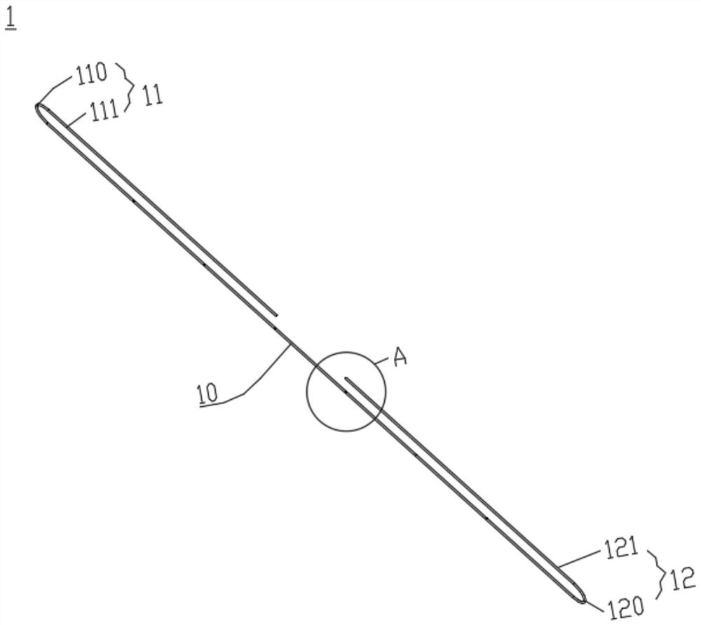
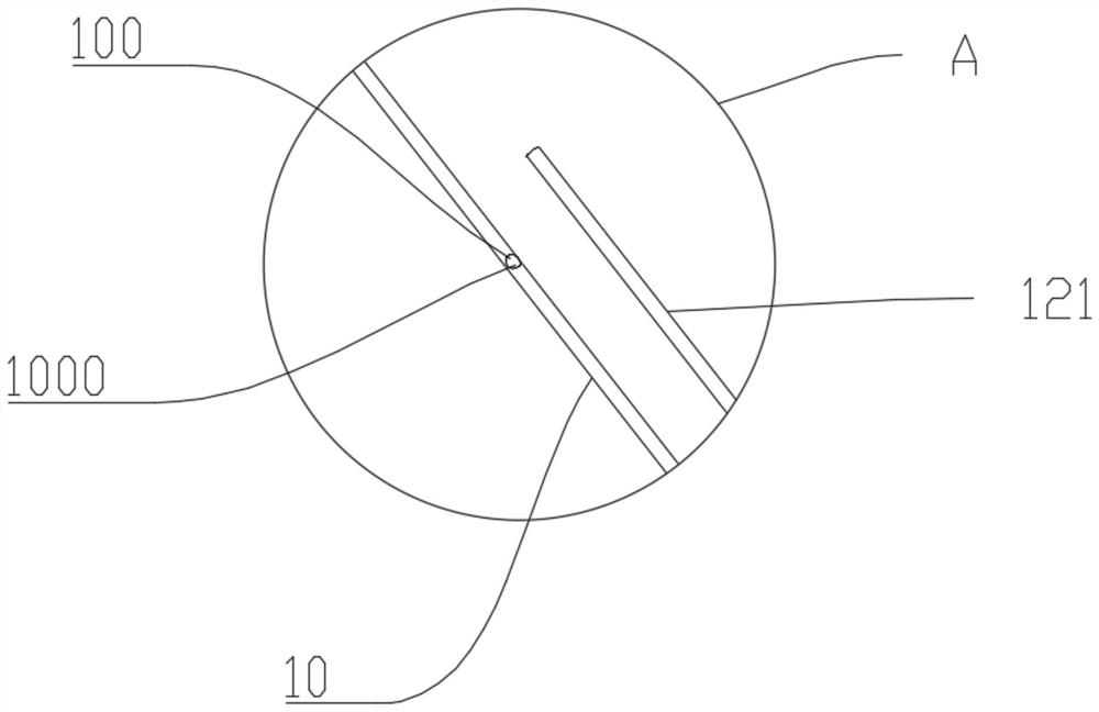
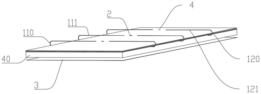
[0005] In order to solve the problem of a single optical fiber output mode in the prior art, the present invention proposes a side-emitting optical fiber and a backlight module with it, which can realize the diversified use of optical fibers

Method used


Image

  • Lateral light-emitting optical fiber and backlight module with same
  • Lateral light-emitting optical fiber and backlight module with same
  • Lateral light-emitting optical fiber and backlight module with same

Examples


Embodiment Construction

[0047] In order to make the object, technical solution and effect of the present invention more clear and definite, the present invention will be further described in detail below with reference to the accompanying drawings and examples. It should be understood that the specific embodiments described here are only used to explain the present invention, not to limit the present invention.

[0048] It should be noted that if there is a directional indication (such as up, down, left, right, front, back...) in the embodiment of the present invention, the directional indication is only used to explain the position in a certain posture (as shown in the accompanying drawing). If the specific posture changes, the directional indication will also change accordingly.

[0049]Liquid crystal flat panel display (LCD) has a very wide range of applications in daily display, from small-sized mobile phones and tablets to large-sized giant-screen TVs will use LCD panels. Now, with Korean panel...


PUM

PropertyMeasurementUnit
depthaaaaaaaaaa
widthaaaaaaaaaa
radiusaaaaaaaaaa

Abstract

The invention discloses a lateral light-emitting optical fiber and a backlight module with the same. The lateral light-emitting optical fiber comprises an optical fiber body, an arc-shaped groove is concavely formed in the side wall of the optical fiber body, and an anti-reflection film is arranged on the groove wall of the arc-shaped groove. Total reflection inside the optical fiber is destroyedby arranging the arc-shaped groove, and meanwhile, the anti-reflection film is arranged on the groove wall of the arc-shaped groove, so that the reflection effect of the arc-shaped groove on light canbe improved, the light which is destroyed and totally reflected in the optical fiber is refracted out from the other side, opposite to the side provided with the limiting groove, of the optical fiber, and lateral light emitting is further achieved.

Description

technical field [0001] The invention relates to the field of optical fiber technology, in particular to a side-emitting optical fiber and a backlight module with the same. Background technique [0002] Traditional optical fiber is composed of core, cladding and coating. The core completes the transmission of light, and the refractive index of the cladding and the core is different, so that the light can be transmitted in the form of total reflection in the core. [0003] However, in the prior art, the light transmission of the optical fiber is generally transmitted from one end of the optical fiber to the other end of the optical fiber, and the light output mode is single, which is not conducive to the diversified use of the optical fiber. [0004] Therefore, the prior art still needs to be improved. Contents of the invention [0005] In order to solve the problem of a single light output mode of the optical fiber in the prior art, the present invention proposes a side-e...

Claims


Application Information

Patent Timeline
Patent Type & Authority Applications(China)
IPC IPC(8): G02F1/13357
CPCG02F1/133605G02F1/133606
Inventor 沈凯锋吴章强何健僖
Owner 深圳康佳电子科技有限公司
Why Eureka
Try Eureka