
Method for evaluating protection effect of newly-built tunnel grouting ring on existing shield tunnel

A technology of shield tunneling and grouting ring, applied in the direction of instruments, data processing applications, geometric CAD, etc., can solve the problems of uncontrollable precision, single factor analysis of grouting ring, etc., and achieve the effect of accurate calculation results

Active Publication Date: 2021-01-08
ZHEJIANG UNIV CITY COLLEGE
View PDF5 Cites 4 Cited by
  • Summary
  • Abstract
  • Description
  • Claims
  • Application Information

AI Technical Summary

Problems solved by technology

[0005] The purpose of the present invention is to provide a method for evaluating the protection effect of a new tunnel grouting ring on an existing shield tunnel, so as to solve the difficulty in the accuracy of the existing numerical simulation method, measured data analysis method, and scaled-down model experimental method in the calculation process. Problems with control or inability to perform single factor analysis on grouting rings

Method used

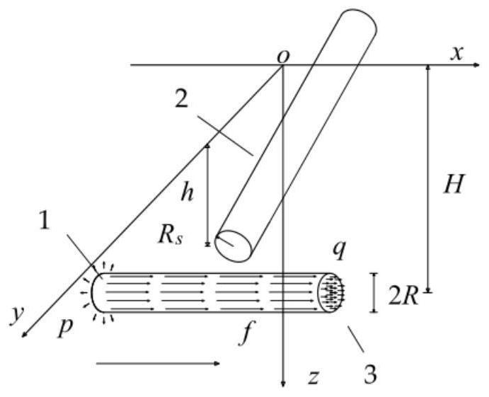
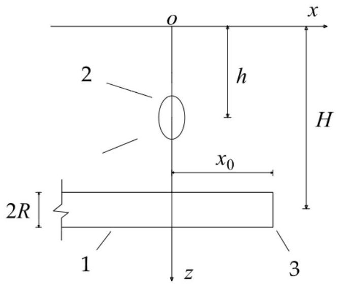

Image

  • Method for evaluating protection effect of newly-built tunnel grouting ring on existing shield tunnel
  • Method for evaluating protection effect of newly-built tunnel grouting ring on existing shield tunnel
  • Method for evaluating protection effect of newly-built tunnel grouting ring on existing shield tunnel

Examples


Embodiment Construction

[0030] The present invention will be further described below in conjunction with the examples. The description of the following examples is provided only to aid the understanding of the present invention. It should be pointed out that for those skilled in the art, without departing from the principle of the present invention, some improvements and modifications can be made to the present invention, and these improvements and modifications also fall within the protection scope of the claims of the present invention.

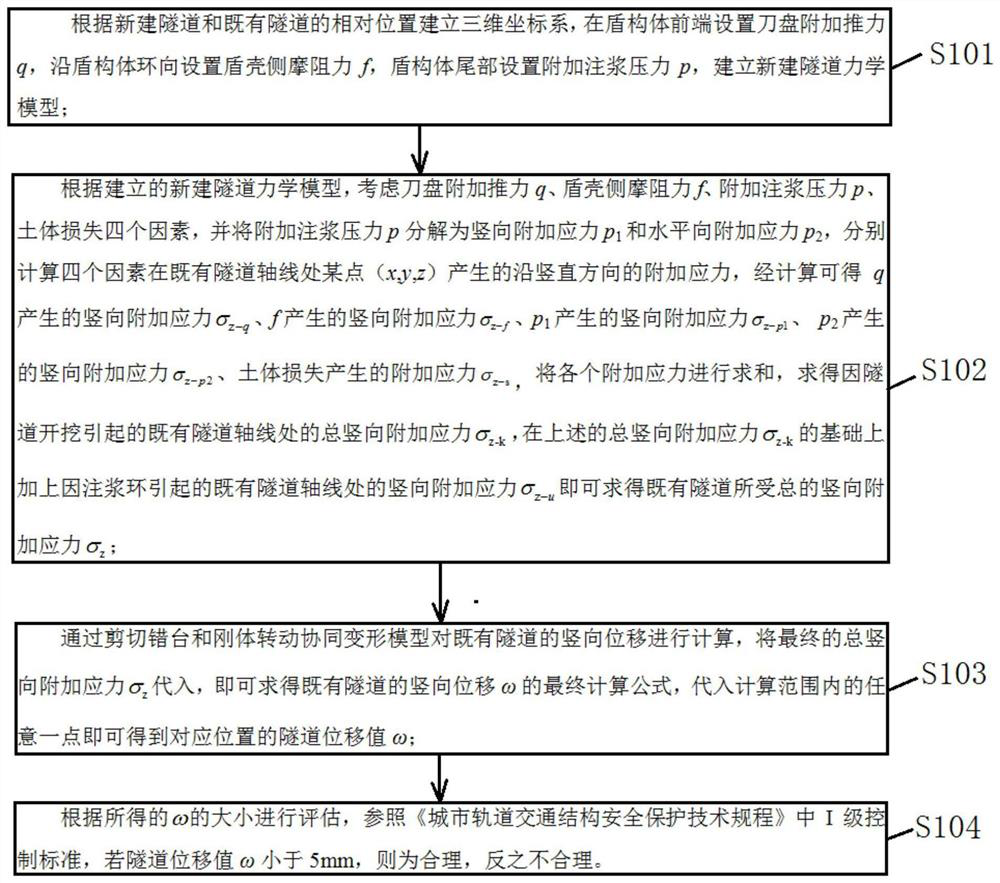
[0031] Such as figure 1 As shown, the embodiment of the present invention provides a calculation method for calculating the displacement of an existing tunnel under the influence of the grouting ring of a new tunnel, including the following steps:

[0032] Step S101, establish a three-dimensional coordinate system according to the relative positions of the newly-built tunnel and the existing tunnel, and establish a mechanical model: set the additional thrust q of...


PUM


Abstract

The invention discloses a method for evaluating the protection effect of a newly-built tunnel grouting ring on an existing shield tunnel. The method comprises steps of a three-dimensional coordinate system and a grouting ring mechanical calculation model being established according to the relative positions of a newly-built tunnel, an existing tunnel and the grouting ring; according to the established grouting ring mechanical model, the influence process on the surrounding soil layer being simulated through volume expansion of the grouting ring, and a formula for solving the additional stressof the surrounding soil layer caused by expansion of the grouting ring being deduced by utilizing a random medium theory; considering the influence of excavation of the newly-built tunnel and volume expansion of the grouting ring, and calculating the total vertical additional stress at the axis of the existing tunnel under the combined action of the excavation and the grouting ring; substituting the total vertical additional stress into the shear slab staggering and rigid body rotation cooperative deformation model to obtain the vertical displacement of the existing tunnel, and evaluating therationality of a tunnel underneath pass scheme and a grouting ring setting scheme according to the obtained vertical displacement of the tunnel. The method can be designed and optimized through repeated adjustment of parameters and multiple times of substitution checking calculation.

Description

technical field [0001] The invention belongs to the technical field of underground engineering, and in particular relates to a method for evaluating the protective effect of a newly-built tunnel grouting ring on an existing shield tunnel, which is suitable for projects in which a grouting ring is installed behind the wall of a newly-built tunnel for reinforcement, especially for shield tunneling at short distances In the existing tunnel engineering, it is especially suitable for analyzing the protective effect of the grouting ring on the existing tunnel. Background technique [0002] With the development of urban subway construction, more and more subway pipelines appear in the limited shallow ground space, and it is inevitable that new shield tunnels will pass through existing tunnels at close range. The short-distance crossing of the shield tunnel will cause deformation of the surrounding soil and redistribution of soil stress, which will affect the structural safety of th...

Claims


Application Information

Patent Timeline
Patent Type & Authority Applications(China)
IPC IPC(8): G06Q10/06G06F30/13G06Q50/08G06F119/14
CPCG06Q10/06393G06F30/13G06Q50/08G06F2119/14
Inventor 魏纲齐永洁王钦谢宇章丽莎刁红国王新泉陈斌
Owner ZHEJIANG UNIV CITY COLLEGE
Learn More