
Method for quickly judging disassembly and assembly sequence of aero-engine core part device

A technology for aero-engines and parts, applied in the field of images, can solve the problems of poor adaptability, waste of manpower and time, waste of manpower and resource costs, etc., to improve robustness and accuracy, reduce uncertainty, and optimize The effect of the discriminant effect

Active Publication Date: 2021-01-08
YANSHAN UNIV
View PDF7 Cites 4 Cited by
  • Summary
  • Abstract
  • Description
  • Claims
  • Application Information

AI Technical Summary

Problems solved by technology

[0002] In some aero-engines that strictly require the disassembly sequence, especially when the parts involved have similar slots, if there are continuous operation steps wrong, it is easy to cause damage to the core parts of the aero-engine. If some irreversible disassembly The installation process is likely to cause huge economic losses
However, today's methods are extremely wasteful of manpower and resource costs. Operators with extensive experience are often required to disassemble and assemble aero-engines. Although high accuracy can be guaranteed, training skilled operators is indeed a waste of manpower. and time, and once the operation is wrong, it will pay a great cost and price
However, the current visual methods rely heavily on a large number of feature engineering to achieve target matching under the existing conditions. These methods are not very adaptable. Changes can have fatal effects

Method used


Image

  • Method for quickly judging disassembly and assembly sequence of aero-engine core part device
  • Method for quickly judging disassembly and assembly sequence of aero-engine core part device
  • Method for quickly judging disassembly and assembly sequence of aero-engine core part device

Examples


Embodiment Construction

[0044]The following will clearly and completely describe the technical solutions in the embodiments of the present invention with reference to the drawings in the embodiments of the present invention. Based on the embodiments of the present invention, all other embodiments obtained by persons of ordinary skill in the art without making creative efforts belong to the protection scope of the present invention.

[0045] It should be noted that, unless otherwise specified, the technical terms or scientific terms used in this application shall have the usual meanings understood by those skilled in the art to which the present invention belongs.

[0046] The present invention will be described in more detail below in conjunction with the accompanying drawings and specific embodiments, taking the relevant components of the core components of the V6 gasoline aeroengine as an example:

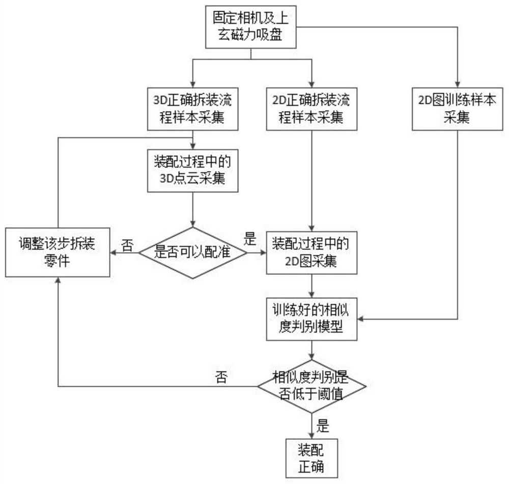
[0047] Depend on figure 1 , this example is a specific implementation flow chart based on the disas...


PUM


Abstract

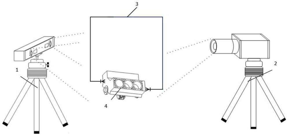
The invention discloses a method for quickly judging the disassembly and assembly sequence of an aero-engine core part device, and the device comprises a 3D camera, a 2D camera and an engine core partfixing device, the 3D camera collects 3D point cloud, the 2D camera collects a 2D image of a key part, and the engine core part fixing device fixes a detected object. Finally, the category and the coordinate position of the part in the acquired image are obtained. Whether the disassembly and assembly sequence of the aero-engine core part device is correct or not is judged according to the acquired images. The judging method comprises the following steps: S1, registering a standard image of a correct dismounting step with a current collection point cloud picture; S2, judging the point cloud picture which cannot be registered as a disassembly and assembly error, and comparing the similarity of the key part of a 2D image which can be registered; and S3, judging that the 2D image passes the similarity comparison as correct disassembly and assembly, otherwise, judging that the 2D image passes the similarity comparison as wrong disassembly and assembly. According to the implementation method, the disassembly and assembly sequence judgment precision can be obviously improved, the judgment error caused by inaccurate disassembly and assembly parts of small parts is overcome, and end-to-endimplementation can be realized.

Description

technical field [0001] The invention belongs to the field of images, and particularly relates to a comparison method based on 3D point cloud registration and fusion of 2D image similarity, which is used to quickly determine whether the assembly and disassembly sequence of the core parts and components of the aero-engine that strictly requires a fixed process in the industry is correct or not judge. Background technique [0002] In some aero-engines that strictly require the disassembly sequence, especially when the parts involved have similar slots, if there are continuous operation steps wrong, it is easy to cause damage to the core parts of the aero-engine. If some irreversible disassembly The installation process is likely to cause huge economic losses. However, today's methods are extremely wasteful of manpower and resource costs. Operators with extensive experience are often required to disassemble and assemble aero-engines. Although high accuracy can be guaranteed, tr...

Claims


Application Information

Patent Timeline
Patent Type & Authority Applications(China)
IPC IPC(8): G06T7/00G06T7/33
CPCG06T7/001G06T7/33G06T2207/30164
Inventor 张立国刘博金梅李枫孙胜春张少阔张子豪郎梦园张勇
Owner YANSHAN UNIV
Learn More