Multi-purpose fixture tool for manipulation training
A fixer, multi-functional technology, applied in the field of appliances, can solve problems such as easy to become monotonous
- Summary
- Abstract
- Description
- Claims
- Application Information
AI Technical Summary
Problems solved by technology
Method used
Image
Examples
Embodiment 1
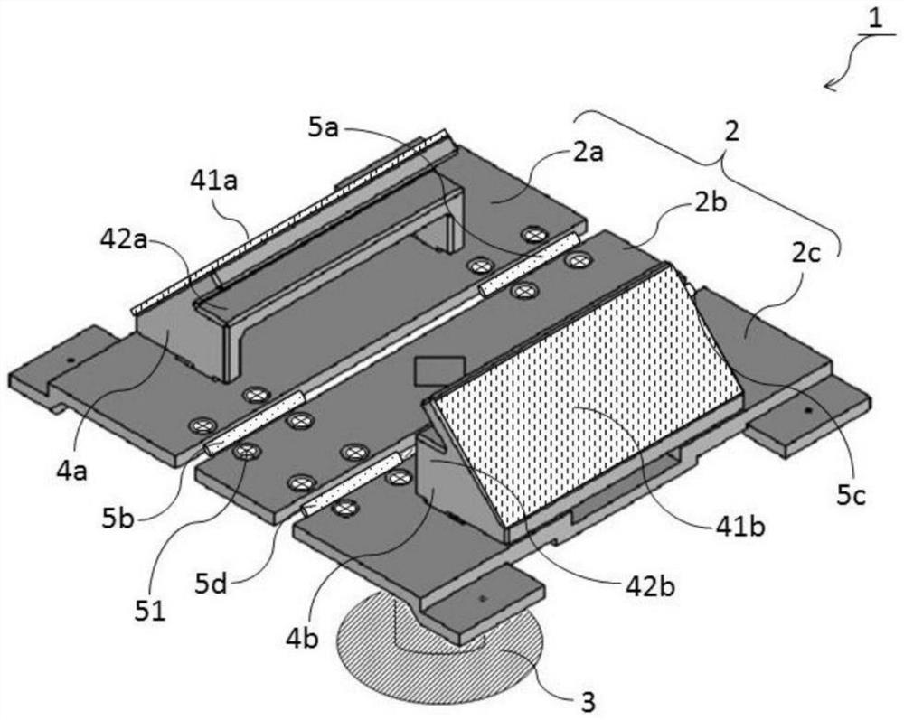
[0065] figure 1 A perspective view of the multifunctional holder according to Example 1 is shown. Such as figure 1 As shown, the multifunctional fixer 1 is composed of a plate connecting body 2, a supporting foot 3 and holding parts (4a, 4b). The plate connecting body 2 is composed of plates (2a-2c), and is rotatably connected by hinges (5a-5d). The specific structure will refer to figure 2 and image 3 to describe.
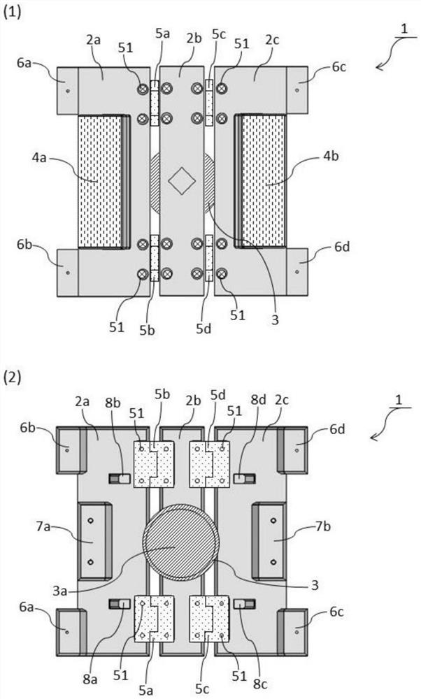
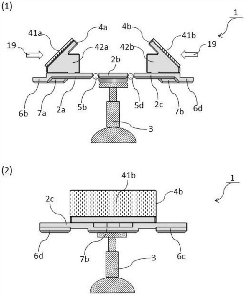
[0066] figure 2 and image 3 It is the external view of the multifunctional holder related to embodiment 1, figure 2 (1) shows a plan view, figure 2 (2) shows the bottom view. also, image 3 (1) shows the front view, image 3 (2) shows the right side view.
[0067] Such as figure 2 As shown in (1), the hinges (5a, 5b) are fixed on the plate 2a and the plate 2b with screws 51 . In addition, the hinges (5c, 5d) are fixed on the plate 2b and the plate 2c using screws 51 . Through the hinges (5a-5d), the plate block 2a and the plate 2b or the plat...
Embodiment 2
[0094] Figure 7 A perspective view of the multifunctional fixer of Embodiment 2 is shown. Such as Figure 7 As shown, the multifunctional fixer 10 is composed of a board connecting body 2, a supporting leg 3 and a magnet clip (9a-9d). The supporting feet 3 are installed under the plate connecting body 2 . The magnet clip 9a is attached to the clip fixing portion 6a made of ferromagnetic metal. Similarly, the magnet clips 9b are mounted on the clip fixing portion 6b, the magnet clips 9c are mounted on the clip fixing portion 6c, and the magnet clips 9d are mounted on the clip fixing portion 6d.
[0095] In the multifunctional holder 10, the holding members (4a, 4b) are removed from the multifunctional holder 1 shown in the first embodiment. By removing the holding members (4a, 4b), the plate connecting body 2 has a substantially planar shape, and becomes a shape suitable for arranging sheet-like objects.
[0096] In addition, the panel connecting body 2 is composed of pan...
Embodiment 3
[0107] Figure 11 Shown is an explanatory diagram of the multifunctional holder according to the third embodiment. Such as Figure 11 As shown, in the multifunctional holder 100, the holding member 4c is mounted on the panel 2c. The holding part 4c is provided with a surface hook and loop fastener 41c, so that it is approximately parallel to the surface of the plate.
[0108] Therefore, if the panel 2c to which the holding member 4c is attached is bent upward by approximately 90°, not only the panel 2c but also the surface fastener 41c will be at right angles to the panels (2a, 2b). In this state, the organ model 18 can be attached to the holding member 4c by the surface hook and loop fastener 41c, and the training for the organ model 18 in the vertical state can be performed.
[0109] (other embodiments)
[0110] At least one of the plate 2a and the holding part 4a, or the plate 2b and the holding part 4b may be connected by a joint mechanism such as a hinge.
PUM
 Abstract
Description
Claims
Application Information
 - R&D
- Intellectual Property
- Life Sciences
- Materials
- Tech Scout
- Unparalleled Data Quality
- Higher Quality Content
- 60% Fewer Hallucinations
Browse by: Latest US Patents, China's latest patents, Technical Efficacy Thesaurus, Application Domain, Technology Topic, Popular Technical Reports.
© 2025 PatSnap. All rights reserved.Legal|Privacy policy|Modern Slavery Act Transparency Statement|Sitemap|About US| Contact US: help@patsnap.com


