Vibration feedback measuring device based on Internet of Things

A vibration feedback and measurement device technology, which is applied in the direction of measurement devices, vibration measurement in solids, earthquake measurement, etc., can solve the problems of supporting spring fatigue, reduced service life, and reduced precision, and achieves improved service life, strong practicability, and Effects of Changing the Measurement Range

Pending Publication Date: 2019-11-05
武汉优斯特传感器科技有限公司
View PDF0 Cites 0 Cited by
  • Summary
  • Abstract
  • Description
  • Claims
  • Application Information

AI Technical Summary

Problems solved by technology

In this case, we must use another measurement method of the seismometer to measure, that is, to use the inertial seismometer. When the inertial mechanical seismometer measures the earthquake, the seismometer is directly fixed on the measured vibration. At the measuring point of the object, when the sensor shell moves with the vibrating object to be measured, the inertial mass supported by the supporting spring will move relative to the shell, and the recording pen installed on the mass block can record the distance between the mass element and the shell. The relative vibration displacement amplitude, and then use the relational expression of the relative vibration displacement between the inertial mass and the shell to obtain the absolute vibration displacement waveform of the measured object. However, if the inertial mass supported by the supporting spring is used, once the finished product is manufactured , the measurement range is fixed, the adaptability is low, and when the support spring is used, the fatigue of the support spring will be caused after long-term use, resulting in reduced accuracy and reduced service life. Vibration Feedback Measuring Device

Method used


Image

  • Vibration feedback measuring device based on Internet of Things
  • Vibration feedback measuring device based on Internet of Things
  • Vibration feedback measuring device based on Internet of Things

Examples


Embodiment Construction

[0020] In order to make the technical means, creative features, goals and effects achieved by the present invention easy to understand, the present invention will be further described below in conjunction with specific embodiments.

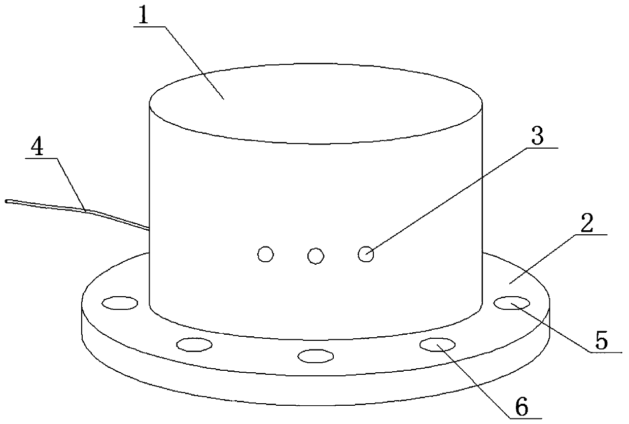
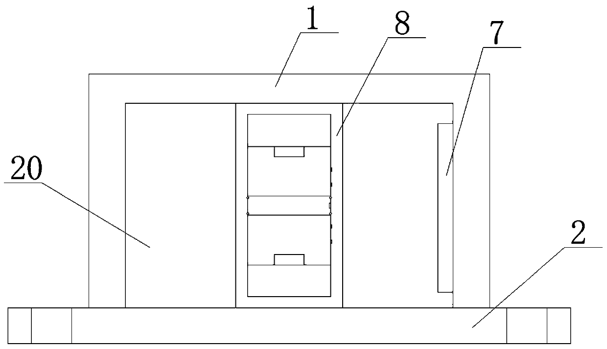
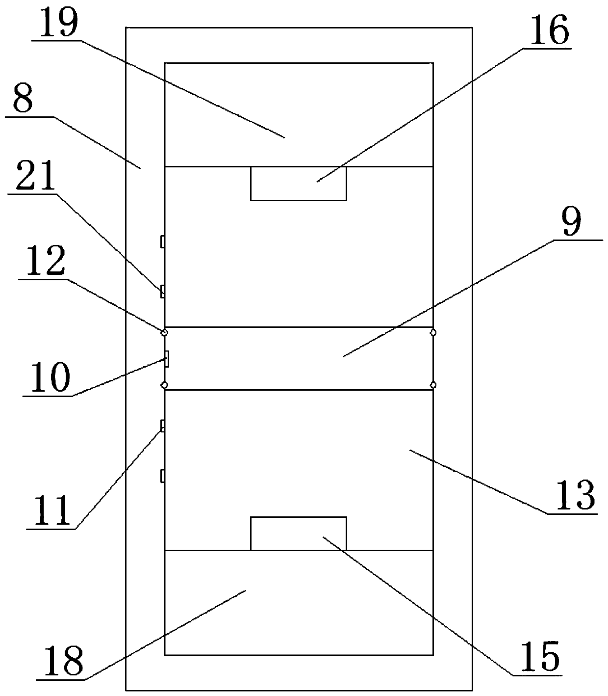
[0021] see Figure 1 to Figure 4 , the present invention provides a technical solution: a vibration feedback measurement device based on the Internet of Things, including a housing 1, an installation base 2 and an intelligent processing system, an over-range indicator light 3 is fixedly installed on the front side of the housing 1, and the One side of the casing 1 is connected with a power cord 4, and the bottom of the casing 1 is provided with an installation groove 20, and the casing 1 is fixedly installed at the center of the top of the installation base 2, and the inner side wall of the installation groove 20 is A circuit board 7 is installed, and a measuring base 8 is fixedly installed on the top of the mounting base 2, and the top of the mea...


PUM


Abstract

The invention provides a vibration feedback measuring device based on the Internet of Things. The device comprises a shell, an installation base and an intelligent processing system, a super-range indicator light is fixedly installed on the front side of the shell, a power line is connected with one side of the shell, and an installation groove is formed in the bottom of the shell; the shell is fixedly installed in the center of the top of the installation base, a circuit board is installed on the inner side wall of one side of the installation groove, a measuring base is fixedly installed atthe top of the installation base, and the top of the measuring base is fixedly connected with the inner side wall of the top of the installation groove; a cavity is formed in the measuring base, a magnet mass block is installed in the cavity, a movable electrode slice is fixedly inlaid in one side of the magnet mass block, and a fixed electrode slice is fixedly inlaid in the inner side wall of oneside of the cavity. The vibration feedback measuring device based on the Internet of Things is reasonable in design, the measuring range can be adjusted, and the high adaptability is achieved.

Description

technical field [0001] The invention belongs to the technical field of vibration detection, in particular to a vibration feedback measurement device based on the Internet of Things. Background technique [0002] In the field of engineering vibration testing, there are various testing methods and methods, but according to the measurement methods of various parameters and the physical properties of the measurement process, they can be divided into three categories, mechanical, optical and electrical. It is the simplest form of material motion, so the first thing people think of is to measure vibration by mechanical method, and the mechanical receiving principle of the sensor is based on this. The working and receiving principle of the relative seismometer is to fix the instrument on a fixed support during measurement, so that the vibration direction of the touch rod and the measured object is consistent, and contact the surface of the measured object with the elastic force of ...

Claims


Application Information

Patent Timeline
IPC IPC(8): G01H1/00G01V1/00
CPCG01H1/00G01V1/01
Inventor 张伟
Owner 武汉优斯特传感器科技有限公司
Why Eureka
Try Eureka