Method and device for dual-mode depth measurement

A depth measurement, dual-mode technology, used in measurement devices, distance measurement, line-of-sight measurement, etc., can solve problems such as different measurement ranges and depth accuracy

Active Publication Date: 2019-08-02
IND TECH RES INST
View PDF8 Cites 0 Cited by
  • Summary
  • Abstract
  • Description
  • Claims
  • Application Information

AI Technical Summary

Problems solved by technology

Such methods are insufficient for measurements that require different measurement ranges and depth accuracies

Method used


Image

  • Method and device for dual-mode depth measurement
  • Method and device for dual-mode depth measurement
  • Method and device for dual-mode depth measurement

Examples


Embodiment Construction

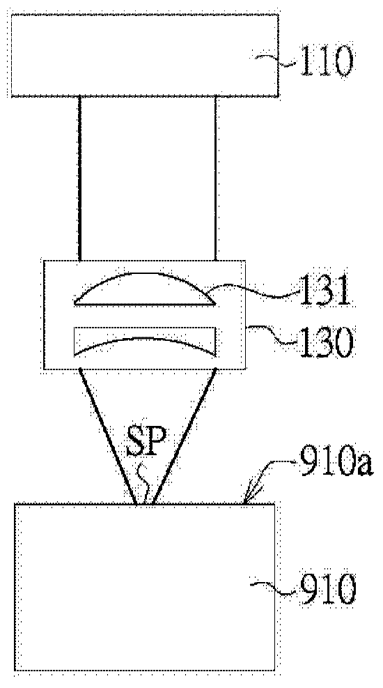
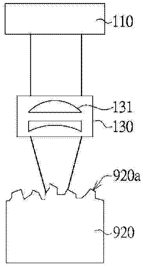
[0034] The invention relates to a device and method for dual-mode depth measurement. Users can perform depth measurement on the surface of an object with mirror reflection or on the surface of an object with texture, and the user can adjust the desired depth measurement accuracy and working range. . The device and method for dual-mode depth measurement of the present invention can obtain the relative distance of the detected object with high precision. figure 1 and figure 2 A schematic diagram showing the light source irradiating the surface of an object in different modes, figure 1 A schematic diagram of the light source 110 and the light emitting optical system 130 in the depth from defocus (DFD) mode is shown. exist figure 1 Among them, an object 910 is, for example, a hard disk or a wafer, which has a mirror-reflecting surface 910a, and the surface 910a is hereinafter referred to as a mirror surface. Such as figure 1 As shown, the light emitting optical system 130 fo...


PUM


Abstract

A device and method for dual-mode depth measurement, which is suitable for measuring depth information of an object, adopts a defocus depth distance measurement mode when the surface of the object presents a mirror surface, or adopts a focus depth distance measurement mode when the surface of the object presents a textured surface. The device includes a light source, a controller, a processor, a light-emitting optical system, an imaging optical system, a beam splitter and a camera. The controller is used to switch to the defocus depth distance measurement mode or the focus depth distance measurement mode. The light-emitting optical system focuses the light beam emitted from the light source on the object surface in the defocus depth distance measurement mode and A beam of uniform illumination illuminates the surface of the object.

Description

technical field [0001] The invention relates to a dual-mode depth measurement method and device, and in particular to a small-scale depth measurement. Background technique [0002] In the field of Automatic Optical Inspection (AOI), depth and distance measurement occupy an important position. Some techniques, such as chromatic confocal spectroscopy (chromatic confocalspectroscopy), white light interferometry (white light interferometry), conoscopic holography (conoscopic holography), triangulation, depth from focus (DFF), depth from defocus (depth fromdefocus, DFD), etc., can perform related measurements. [0003] The depth measurement based on defocus depth is to obtain depth information by analyzing the defocus amount of one or more captured images. Furthermore, the beam is focused into a light spot and projected on the surface of the object to be measured, and the size of the light spot is used to infer depth information. The accuracy of the estimated depth and the mea...

Claims


Application Information

Patent Timeline
Patent Type & Authority Patents(China)
IPC IPC(8): G01B11/22
CPCG01B11/22G06T7/571G01B11/026G01B11/0608G02B21/36H04N23/667G01C3/08G06T2207/10028G06T2207/10148
Inventor 安国律多曾坤隆周奕衡
Owner IND TECH RES INST
Why Eureka
Try Eureka